11.3 Lewis Symbols and Structures
Learning Objectives
By the end of this section, you will be able to:
- Write Lewis symbols for neutral atoms and ions
- Draw Lewis structures depicting the bonding in simple molecules
Thus far in this chapter, we have discussed the various types of bonds that form between atoms and/or ions. In all cases, these bonds involve the sharing or transfer of valence shell electrons between atoms. In this section, we will explore the typical method for depicting valence shell electrons and chemical bonds, namely Lewis symbols and Lewis structures.
Lewis Symbols
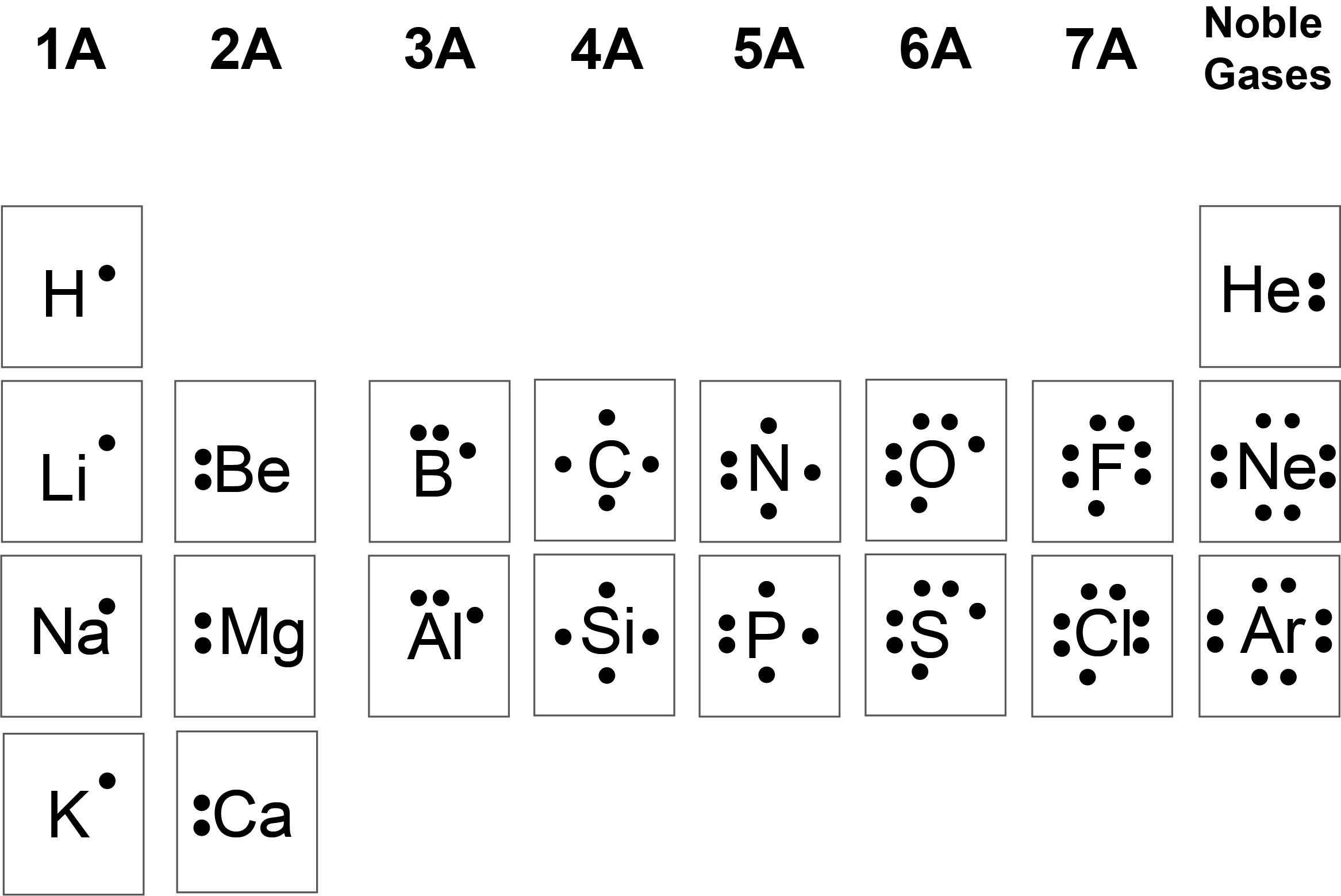
We use Lewis symbols to describe valence electron configurations of atoms and monatomic ions. A Lewis symbol consists of an elemental symbol surrounded by one dot for each of its valence electrons as shown in Figure 11.3a.

![A table is shown that has three columns and nine rows. The header row reads “Atoms,” “Electronic Configuration,” and “Lewis Symbol.” The first column contains the words “sodium,” “magnesium,” “aluminum,” “silicon,” “phosphorus,” “sulfur,” “chlorine,” and “argon.” The second column contains the symbols and numbers “[ N e ] 3 s superscript 2,” “[ N e ] 3 s superscript 2, 3 p superscript 1,” “[ N e ] 3 s superscript 2, 3 p superscript 2,” “[ N e ] 3 s superscript 2, 3 p superscript 3,” “[ N e ] 3 s superscript 2, 3 p superscript 4,” “[ N e ] 3 s superscript 2, 3 p superscript 5,” and “[ N e ] 3 s superscript 2, 3 p superscript 6.” The third column contains Lewis structures for N a with one dot, M g with two dots, A l with three dots, Si with four dots, P with five dots, S with six dots, C l with seven dots, and A r with eight dots.](https://ecampusontario.pressbooks.pub/app/uploads/sites/3164/2023/03/CNX_Chem_07_03_3rowLewis.jpg)
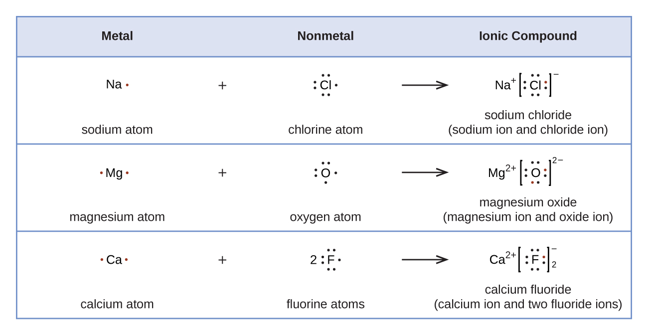
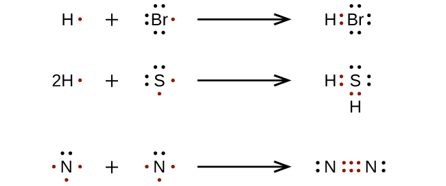
Lewis symbols can also be used to illustrate the formation of cations from atoms, as shown here for sodium and calcium:

Likewise, they can be used to show the formation of anions from atoms, as shown here for chlorine and sulfur:
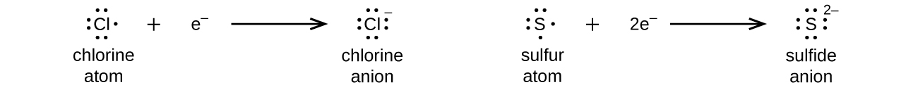
Figure 11.3f demonstrates the use of Lewis symbols to show the transfer of electrons during the formation of ionic compounds.
Lewis Structures
We also use Lewis symbols to indicate the formation of covalent bonds, which are shown in Lewis structures, drawings that describe the bonding in molecules and polyatomic ions. For example, when two chlorine atoms form a chlorine molecule, they share one pair of electrons:
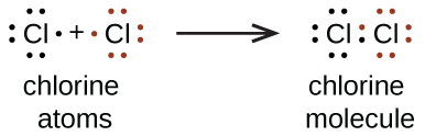
The Lewis structure indicates that each Cl atom has three pairs of electrons that are not used in bonding (called lone pairs) and one shared pair of electrons (written between the atoms). A dash (or line) is sometimes used to indicate a shared pair of electrons:
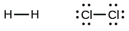
A single shared pair of electrons is called a single bond. Each Cl atom interacts with eight valence electrons: the six in the lone pairs and the two in the single bond.
The Octet Rule
The other halogen molecules (F2, Br2, I2, and At2) form bonds like those in the chlorine molecule: one single bond between atoms and three lone pairs of electrons per atom. This allows each halogen atom to have a noble gas electron configuration. The tendency of main group atoms to form enough bonds to obtain eight valence electrons is known as the octet rule.
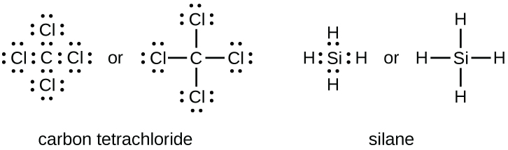
The number of bonds that an atom can form can often be predicted from the number of electrons needed to reach an octet (eight valence electrons); this is especially true of the nonmetals of the second period of the periodic table (C, N, O, and F). For example, each atom of a group 14 element has four electrons in its outermost shell and therefore requires four more electrons to reach an octet. These four electrons can be gained by forming four covalent bonds, as illustrated here for carbon in CCl4 (carbon tetrachloride) and silicon in SiH4 (silane). Because hydrogen only needs two electrons to fill its valence shell, it is an exception to the octet rule. The transition elements and inner transition elements also do not follow the octet rule:
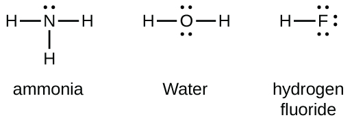
Group 15 elements such as nitrogen have five valence electrons in the atomic Lewis symbol: one lone pair and three unpaired electrons. To obtain an octet, these atoms form three covalent bonds, as in NH3 (ammonia). Oxygen and other atoms in group 16 obtain an octet by forming two covalent bonds:
Double and Triple Bonds
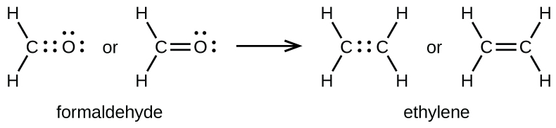
As previously mentioned, when a pair of atoms shares one pair of electrons, we call this a single bond. However, a pair of atoms may need to share more than one pair of electrons in order to achieve the requisite octet. A double bond forms when two pairs of electrons are shared between a pair of atoms, as between the carbon and oxygen atoms in CH2O (formaldehyde) and between the two carbon atoms in C2H4 (ethylene):
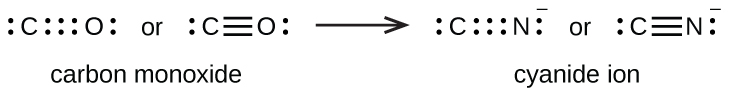
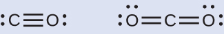
A triple bond forms when three electron pairs are shared by a pair of atoms, as in carbon monoxide (CO) and the cyanide ion (CN–):
Writing Lewis Structures with the Octet Rule
For very simple molecules and molecular ions, we can write the Lewis structures by merely pairing up the unpaired electrons on the constituent atoms (Figure 11.3m):
For more complicated molecules and molecular ions, it is helpful to follow the step-by-step procedure outlined here:
- Determine the total number of valence (outer shell) electrons. For cations, subtract one electron for each positive charge. For anions, add one electron for each negative charge.
- Draw a skeleton structure of the molecule or ion, arranging the atoms around a central atom. (Generally, the least electronegative element should be placed in the centre.) Connect each atom to the central atom with a single bond (one electron pair).
- Distribute the remaining electrons as lone pairs on the terminal atoms (except hydrogen), completing an octet around each atom.
- Place all remaining electrons on the central atom.
- Rearrange the electrons of the outer atoms to make multiple bonds with the central atom in order to obtain octets wherever possible.
Let us determine the Lewis structures of SiH4, CHO2−, NO+, and OF2 as examples in following this procedure:
- Determine the total number of valence (outer shell) electrons in the molecule or ion.
- For a molecule, we add the number of valence electrons on each atom in the molecule:
[latex]\begin{array}{r r l} \text{SiH}_4 & & \\[1em] & \text{Si: 4 valence electrons/atom} \times 1 \;\text{atom} & = 4 \\[1em] \rule[-0.5ex]{21em}{0.1ex}\hspace{-21em} + & \text{H: 1 valence electron/atom} \times 4 \;\text{atoms} & = 4 \\[1em] & & = 8 \;\text{valence electrons} \end{array}[/latex]
- For a negative ion, such as CHO2−, we add the number of valence electrons on the atoms to the number of negative charges on the ion (one electron is gained for each single negative charge):
[latex]\begin{array}{r r l} {\text{CHO}_2}^{-} & & \\[1em] & \text{C: 4 valence electrons/atom} \times 1 \;\text{atom} & = 4 \\[1em] & \text{H: 1 valence electron/atom} \times 1 \;\text{atom} & = 1 \\[1em] & \text{O: 6 valence electrons/atom} \times 2 \;\text{atoms} & = 12 \\[1em] \rule[-0.5ex]{21.5em}{0.1ex}\hspace{-21.5em} + & 1\;\text{additional electron} & = 1 \\[1em] & & = 18 \;\text{valence electrons} \end{array}[/latex]
- For a positive ion, such as NO+, we add the number of valence electrons on the atoms in the ion and then subtract the number of positive charges on the ion (one electron is lost for each single positive charge) from the total number of valence electrons:
[latex]\begin{array}{r r l} \text{NO}^{+} & & \\[1em] & \text{N: 5 valence electrons/atom} \times 1 \;\text{atom} & = 5 \\[1em] & \text{O: 6 valence electrons/atom} \times 1 \;\text{atom} & = 6 \\[1em] \rule[-0.5ex]{21em}{0.1ex}\hspace{-21em} + & -1 \;\text{electron (positive charge)} & = -1 \\[1em] & & = 10 \;\text{valence electrons} \end{array}[/latex]
- Since OF2 is a neutral molecule, we simply add the number of valence electrons:
[latex]\begin{array}{r r l} \text{OF}_{2} & & \\[1em] & \text{O: 6 valence electrons/atom} \times 1 \;\text{atom} & = 6 \\[1em] \rule[-0.5ex]{21em}{0.1ex}\hspace{-21em} + & \text{F: 7 valence electrons/atom} \times 2 \;\text{atoms} & = 14 \\[1em] & & = 20 \;\text{valence electrons} \end{array}[/latex]
- For a molecule, we add the number of valence electrons on each atom in the molecule:
- Draw a skeleton structure of the molecule or ion, arranging the atoms around a central atom and connecting each atom to the central atom with a single (one electron pair) bond. (Note that we denote ions with brackets around the structure, indicating the charge outside the brackets:)
Figure 11.3n: Skeletal structures (incomplete Lewis structures) of SiH4, CHO2−, NO+, and OF2. Step 2 of process to draw Lewis structure (credit: Chemistry (OpenStax), CC BY 4.0). When several arrangements of atoms are possible, as for CHO2−, we must use experimental evidence to choose the correct one. In general, the less electronegative elements are more likely to be central atoms. In CHO2−, the less electronegative carbon atom occupies the central position with the oxygen and hydrogen atoms surrounding it. Other examples include P in POCl3, S in SO2, and Cl in ClO4−. An exception is that hydrogen is almost never a central atom. As the most electronegative element, fluorine also cannot be a central atom.
- Distribute the remaining electrons as lone pairs on the terminal atoms (except hydrogen) to complete their valence shells with an octet of electrons.
- There are no remaining electrons on SiH4, so it is unchanged:
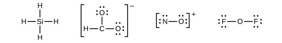
Figure 11.3o: Lewis structure of SiH4. Skeletal structures (incomplete Lewis structures) of CHO2−, NO+, and OF2. Step 3 of process to draw Lewis structure (credit: Chemistry (OpenStax), CC BY 4.0).
- There are no remaining electrons on SiH4, so it is unchanged:
- Place all remaining electrons on the central atom.
- For SiH4, CHO2−, and NO+, there are no remaining electrons; we already placed all of the electrons determined in Step 1.
- For OF2, we had 16 electrons remaining in Step 3, and we placed 12, leaving 4 to be placed on the central atom:
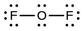
Figure 11.3p: Lewis structure of OF2. Step 4 of process to draw Lewis structure (credit: Chemistry (OpenStax), CC BY 4.0).
- Rearrange the electrons of the outer atoms to make multiple bonds with the central atom in order to obtain octets wherever possible.
- SiH4: Si already has an octet, so nothing needs to be done.
- CHO2−: We have distributed the valence electrons as lone pairs on the oxygen atoms, but the carbon atom lacks an octet:
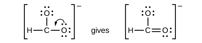
Figure 11.3q: Lewis structure of CHO2−. Step 5 of process to draw Lewis structure (credit: Chemistry (OpenStax), CC BY 4.0). - NO+: For this ion, we added eight valence electrons, but neither atom has an octet. We cannot add any more electrons since we have already used the total that we found in Step 1, so we must move electrons to form a multiple bond:

Figure 11.3r: Incomplete Lewis structure NO+. Step 5 of process to draw Lewis structure (credit: Chemistry (OpenStax), CC BY 4.0). - This still does not produce an octet, so we must move another pair, forming a triple bond:

Figure 11.3s: Lewis structure of NO+. Step 5 of process to draw Lewis structure (credit: Chemistry (OpenStax), CC BY 4.0). - In OF2, each atom has an octet as drawn, so nothing changes.
Example 11.3a
Writing Lewis Structures
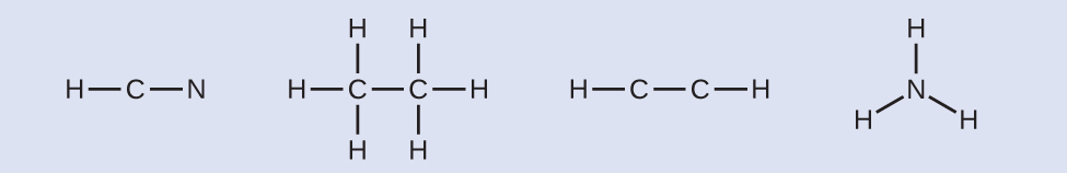
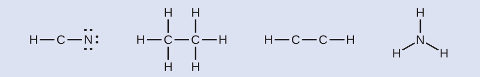
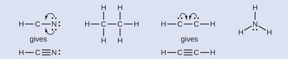
NASA’s Cassini-Huygens mission detected a large cloud of toxic hydrogen cyanide (HCN) on Titan, one of Saturn’s moons. Titan also contains ethane (H3CCH3), acetylene (HCCH), and ammonia (NH3). What are the Lewis structures of these molecules?
Solution
- Calculate the number of valence electrons.
- HCN: (1 × 1) + (4 × 1) + (5 × 1) = 10
- H3CCH3: (1 × 3) + (2 × 4) + (1 × 3) = 14
- HCCH: (1 × 1) + (2 × 4) + (1 × 1) = 10
- NH3: (5 × 1) + (3 × 1) = 8
- Draw a skeleton and connect the atoms with single bonds. Remember that H is never a central atom:
- Where needed, distribute electrons to the terminal atoms:
- HCN: six electrons placed on N.
- H3CCH3: no electrons remain.
- HCCH: no terminal atoms capable of accepting electrons.
- NH3: no terminal atoms capable of accepting electrons.
- Where needed, place remaining electrons on the central atom:
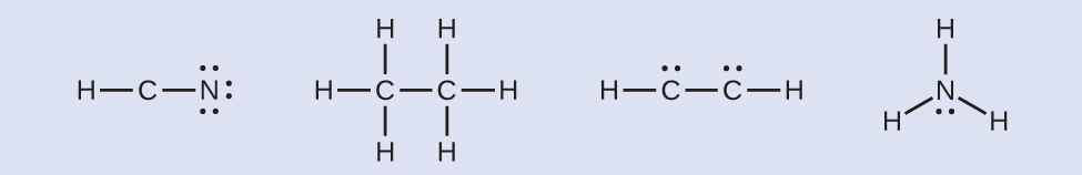
- HCN: no electrons remain.
- H3CCH3: no electrons remain.
- HCCH: four electrons placed on carbon.
- NH3: two electrons placed on nitrogen.
- Where needed, rearrange electrons to form multiple bonds in order to obtain an octet on each atom:
- HCN: form two more C–N bonds.
- H3CCH3: all atoms have the correct number of electrons.
- HCCH: form a triple bond between the two carbon atoms.
- NH3: all atoms have the correct number of electrons.
Exercise 11.3a
Both carbon monoxide, CO, and carbon dioxide, CO2, are products of the combustion of fossil fuels. Both of these gases also cause problems: CO is toxic and CO2 has been implicated in global climate change. What are the Lewis structures of these two molecules?
Check Your Answer[1]
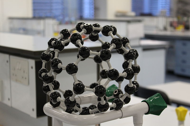
Fullerene Chemistry
Carbon soot has been known to man since prehistoric times, but it was not until fairly recently that the molecular structure of the main component of soot was discovered. In 1996, the Nobel Prize in Chemistry was awarded to Richard Smalley (Figure 11.3t), Robert Curl, and Harold Kroto for their work in discovering a new form of carbon, the C60 buckminsterfullerene molecule (Figure 11.a in Chapter 11 Introduction). An entire class of compounds, including spheres and tubes of various shapes, were discovered based on C60. This type of molecule, called a fullerene, shows promise in a variety of applications. Because of their size and shape, fullerenes can encapsulate other molecules, so they have shown potential in various applications from hydrogen storage to targeted drug delivery systems. They also possess unique electronic and optical properties that have been put to good use in solar powered devices and chemical sensors.
Richard Smalley (1943–2005), a professor of physics, chemistry, and astronomy at Rice University, was one of the leading advocates for fullerene chemistry. Upon his death in 2005, the US Senate honoured him as the “Father of Nanotechnology.”
Learn more about Dr. Smalley by reading the article Richard E. Smalley – Facts [New Tab] on the Nobel Prize website.
Scientists in Action: Dr. Mario J. Molina
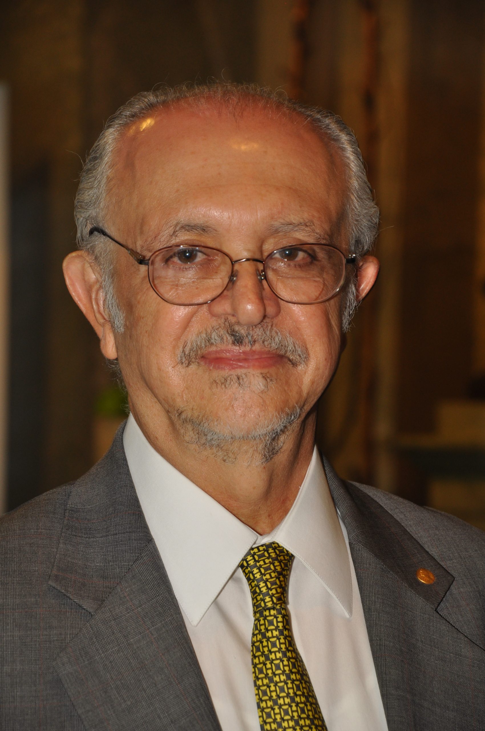
Dr. Mario J. Molina is a Mexican chemist who is best known for his role in the discovery of the impact that CFC’s (chlorofluorocarbons) have on the ozone layer. He was a co-recipient of the Nobel Prize in Chemistry in 1995.
Part of his work included the hypothesis that CFCs in the upper atmosphere could produce a chlorine radical that would catalyze the destruction of ozone.
Cl· + O3 → ClO· + O2
ClO· + O· → Cl· + O2
After data was collected that confirmed this hypothesis, steps were taken by countries across the world to discontinue the use of ozone-damaging compounds. The most significant actions were included in the Montreal Protocol [New Tab].
Dr. Molina is currently a faculty member at UC San Diego and is involved in science outreach.
Watch Dr. Molina address students about his inspiration to become a scientist in this Nobel Prize video on YouTube [New Tab].
Exceptions to the Octet Rule
Many covalent molecules have central atoms that do not have eight electrons in their Lewis structures. These molecules fall into three categories:
- Odd-electron molecules have an odd number of valence electrons, and therefore have an unpaired electron.
- Electron-deficient molecules have a central atom that has fewer electrons than needed for a noble gas configuration.
- Hypervalent molecules have a central atom that has more electrons than needed for a noble gas configuration.
Odd-electron Molecules
We call molecules that contain an odd number of electrons free radicals. Nitric oxide, NO, is an example of an odd-electron molecule; it is produced in internal combustion engines when oxygen and nitrogen react at high temperatures.
To draw the Lewis structure for an odd-electron molecule like NO, we follow the same five steps we would for other molecules, but with a few minor changes:
- Determine the total number of valence (outer shell) electrons. The sum of the valence electrons is 5 (from N) + 6 (from O) = 11. The odd number immediately tells us that we have a free radical, so we know that not every atom can have eight electrons in its valence shell.
- Draw a skeleton structure of the molecule. We can easily draw a skeleton with an N–O single bond:N–O
- Distribute the remaining electrons as lone pairs on the terminal atoms. In this case, there is no central atom, so we distribute the electrons around both atoms. We give eight electrons to the more electronegative atom in these situations; thus oxygen has the filled valence shell:
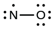
Figure 11.3v: Lewis structure of NO where oxygen has been assigned the eight electrons as it is more electronegative compared to nitrogen (credit: Chemistry (OpenStax), CC BY 4.0). - Place all remaining electrons on the central atom. Since there are no remaining electrons, this step does not apply.
- Rearrange the electrons to make multiple bonds with the central atom in order to obtain octets wherever possible. We know that an odd-electron molecule cannot have an octet for every atom, but we want to get each atom as close to an octet as possible. In this case, nitrogen has only five electrons around it. To move closer to an octet for nitrogen, we take one of the lone pairs from oxygen and use it to form a NO double bond. (We cannot take another lone pair of electrons on oxygen and form a triple bond because nitrogen would then have nine electrons:)
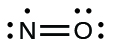
Figure 11.3w: The Lewis structure of NO double bond where the electrons are rearranged to obtain octets where a double bond is formed so that nitrogen can move closer to an octet (credit: Chemistry (OpenStax), CC BY 4.0).
Electron-deficient Molecules
We will also encounter a few molecules that contain central atoms that do not have a filled valence shell. Generally, these are molecules with central atoms from groups 2 and 12, outer atoms that are hydrogen, or other atoms that do not form multiple bonds. For example, in the Lewis structures of beryllium dihydride, BeH2, and boron trifluoride, BF3, the beryllium and boron atoms each have only four and six electrons, respectively. It is possible to draw a structure with a double bond between a boron atom and a fluorine atom in BF3, satisfying the octet rule, but experimental evidence indicates the bond lengths are closer to that expected for B–F single bonds. This suggests the best Lewis structure has three B–F single bonds and an electron deficient boron. The reactivity of the compound is also consistent with an electron deficient boron. However, the B–F bonds are slightly shorter than what is actually expected for B–F single bonds, indicating that some double bond character is found in the actual molecule.
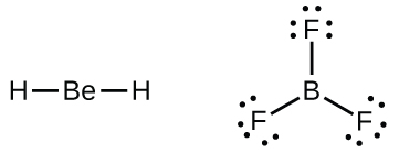
An atom like the boron atom in BF3, which does not have eight electrons, is very reactive. It readily combines with a molecule containing an atom with a lone pair of electrons. For example, NH3 reacts with BF3 because the lone pair on nitrogen can be shared with the boron atom (Figure 11.3y).
Hypervalent Molecules
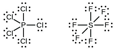
Elements in the second period of the periodic table (n = 2) can accommodate only eight electrons in their valence shell orbitals because they have only four valence orbitals (one 2s and three 2p orbitals). Elements in the third and higher periods (n ≥ 3) have more than four valence orbitals and can share more than four pairs of electrons with other atoms because they have empty d orbitals in the same shell. Molecules formed from these elements are sometimes called hypervalent molecules. Figure 11.3z shows the Lewis structures for two hypervalent molecules, PCl5 and SF6.
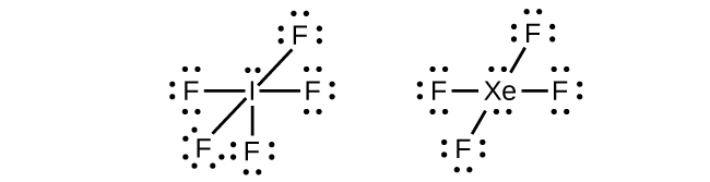
In some hypervalent molecules, such as IF5 and XeF4, some of the electrons in the outer shell of the central atom are lone pairs (Figure 11.3aa).
When we write the Lewis structures for these molecules, we find that we have electrons left over after filling the valence shells of the outer atoms with eight electrons. These additional electrons must be assigned to the central atom.
Example 11.3b
Writing Lewis Structures: Octet Rule Violations
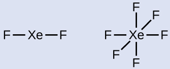
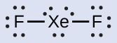
Xenon is a noble gas, but it forms a number of stable compounds. We examined XeF4 earlier. What are the Lewis structures of XeF2 and XeF6?
Solution
We can draw the Lewis structure of any covalent molecule by following the six steps discussed earlier. In this case, we can condense the last few steps, since not all of them apply.
- Calculate the number of valence electrons:XeF2: 8 + (2 × 7) = 22XeF6: 8 + (6 × 7) = 50
- Draw a skeleton joining the atoms by single bonds. Xenon will be the central atom because fluorine cannot be a central atom:
- Distribute the remaining electrons.
- XeF2: We place three lone pairs of electrons around each F atom, accounting for 12 electrons and giving each F atom 8 electrons. Thus, six electrons (three lone pairs) remain. These lone pairs must be placed on the Xe atom. This is acceptable because Xe atoms have empty valence shell d orbitals and can accommodate more than eight electrons. The Lewis structure of XeF2 shows two bonding pairs and three lone pairs of electrons around the Xe atom:
- XeF6: We place three lone pairs of electrons around each F atom, accounting for 36 electrons. Two electrons remain, and this lone pair is placed on the Xe atom:
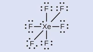
- XeF2: We place three lone pairs of electrons around each F atom, accounting for 12 electrons and giving each F atom 8 electrons. Thus, six electrons (three lone pairs) remain. These lone pairs must be placed on the Xe atom. This is acceptable because Xe atoms have empty valence shell d orbitals and can accommodate more than eight electrons. The Lewis structure of XeF2 shows two bonding pairs and three lone pairs of electrons around the Xe atom:
Exercise 11.3b
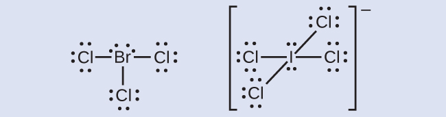
The halogens form a class of compounds called the interhalogens, in which halogen atoms covalently bond to each other. Write the Lewis structures for the interhalogens BrCl3 and ICl4−.
Check Your Answer[2]
Links to Interactive Learning Tools
Explore Lewis Electron Dot Structures from the Physics Classroom.
Explore Drawing Lewis Structures from Alchemie.
Attribution & References
Except where otherwise noted, this page is adapted JR van Haarlem from “4.4 Lewis Symbols and Structures” In General Chemistry 1 & 2 by Rice University, a derivative of Chemistry (Open Stax) by Paul Flowers, Klaus Theopold, Richard Langley & William R. Robinson and is licensed under CC BY 4.0. Access for free at Chemistry (OpenStax)
symbol for an element or monatomic ion that uses a dot to represent each valence electron in the element or ion
diagram showing lone pairs and bonding pairs of electrons in a molecule or an ion
two (a pair of) valence electrons that are not used to form a covalent bond
bond in which a single pair of electrons is shared between two atoms
guideline that states main group atoms will form structures in which eight valence electrons interact with each nucleus, counting bonding electrons as interacting with both atoms connected by the bond
covalent bond in which two pairs of electrons are shared between two atoms
bond in which three pairs of electrons are shared between two atoms
molecule that contains an odd number of electrons
molecule containing at least one main group element that has more than eight electrons in its valence shell
