18.4 Electrode and Cell Potentials

Learning Objectives

By the end of this section, you will be able to:
  • Determine standard cell potentials for oxidation-reduction reactions
  • Use standard reduction potentials to determine the better oxidizing or reducing agent from among several possible choices

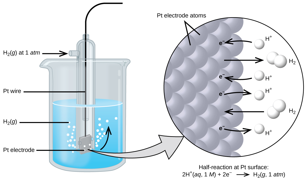
The cell potential in 18.3 – Galvanic Cells results from the difference in the electrical potentials for each electrode. While it is impossible to determine the electrical potential of a single electrode, we can assign an electrode the value of zero and then use it as a reference. The electrode chosen as the zero is shown in Figure 18.4a and is called the standard hydrogen electrode (SHE). The SHE consists of 1 atm of hydrogen gas bubbled through a 1 M HCl solution, usually at room temperature. Platinum, which is chemically inert, is used as the electrode. The reduction half-reaction chosen as the reference is

[latex]2\text{ H}^{+}(aq\text{,}\;1\;M)\;+\;2\text{ e}^{-}\;{\rightleftharpoons}\;\text{H}_2(g\text{,}\;1\;\text{atm})\;\;\;\;\;\;E^{\circ} = 0\;\text{V}[/latex]

E° is the standard reduction potential. The superscript “°” on the E denotes standard conditions (1 bar or 1 atm for gases, 1 M for solutes). The voltage is defined as zero for all temperatures.

The figure shows a beaker just over half full of a blue liquid. A glass tube is partially submerged in the liquid. Bubbles, which are labeled “H subscript 2 ( g )” are rising from the dark grey square, labeled “P t electrode” at the bottom of the tube. A curved arrow points up to the right, indicating the direction of the bubbles. A black wire which is labeled “P t wire” extends from the dark grey square up the interior of the tube through a small port at the top. A second small port extends out the top of the tube to the left. An arrow points to the port opening from the left. The base of this arrow is labeled “H subscript 2 ( g ) at 1 a t m.” A light grey arrow points to a diagram in a circle at the right that illustrates the surface of the P t electrode in a magnified view. P t atoms are illustrated as a uniform cluster of grey spheres which are labeled “P t electrode atoms.” On the grey atom surface, the label “e superscript negative” is shown 4 times in a nearly even vertical distribution to show electrons on the P t surface. A curved arrow extends from a white sphere labeled “H superscript plus” at the right of the P t atoms to the uppermost electron shown. Just below, a straight arrow extends from the P t surface to the right to a pair of linked white spheres which are labeled “H subscript 2.” A curved arrow extends from a second white sphere labeled “H superscript plus” at the right of the P t atoms to the second electron shown. A curved arrow extends from the third electron on the P t surface to the right to a white sphere labeled “H superscript plus.” Just below, an arrow points left from a pair of linked white spheres which are labeled “H subscript 2” to the P t surface. A curved arrow extends from the fourth electron on the P t surface to the right to a white sphere labeled “H superscript plus.” Beneath this atomic view is the label “Half-reaction at P t surface: 2 H superscript plus ( a q, 1 M ) plus 2 e superscript negative right pointing arrow H subscript 2 ( g, 1 a t m ).”
Figure 18.4a: Hydrogen gas at 1 atm is bubbled through 1 M HCl solution. Platinum, which is inert to the action of the 1 M HCl, is used as the electrode. Electrons on the surface of the electrode combine with H+ in solution to produce hydrogen gas (credit: Chemistry (OpenStax), CC BY 4.0).

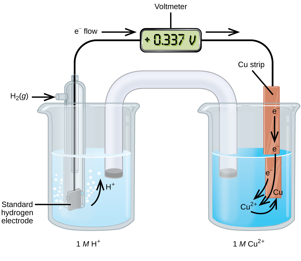
A galvanic cell consisting of a SHE and Cu2+/Cu half-cell can be used to determine the standard reduction potential for Cu2+ (Figure 18.4b). In cell notation, the reaction is

[latex]\text{Pt}(s){\mid}\text{H}_2(g, \text{1 atm}){\mid}\text{H}^{+}(aq\text{,}\;1\;M){\parallel}\text{Cu}^{2+}(aq\text{,}\;1\;M){\mid}\text{Cu}(s)[/latex]

Electrons flow from the anode to the cathode. The reactions, which are reversible, are

[latex]\begin{array}{lr @{{}\longrightarrow{}} l} \text{Anode (oxidation):} & \text{H}_2(g) & \longrightarrow 2\text{ H}^{+}(aq)\;+\;2\text{ e}^{-} \\[0.5em] \text{Cathode (reduction):} & \text{Cu}^{2+}(aq)\;+\;2\text{ e}^{-} & \longrightarrow \text{Cu}(s) \\[0.5em] \hline \\[-0.25em] \text{Overall:} & \text{Cu}^{2+}(aq)\;+\;\text{H}_2(g) & \longrightarrow 2\text{ H}^{+}(aq)\;+\;\text{Cu}(s) \end{array}[/latex]

The standard reduction potential can be determined by subtracting the standard reduction potential for the reaction occurring at the anode from the standard reduction potential for the reaction occurring at the cathode. The minus sign is necessary because oxidation is the reverse of reduction.

[latex]E_{\text{cell}}^{\circ} = E_{\text{cathode}}^{\circ}\;-\;E_{\text{anode}}^{\circ}[/latex]
[latex]+0.34\;\text{V} = E_{\text{Cu}^{2+}/\text{Cu}}^{\circ}\;-\;E_{\text{H}^{+}/\text{H}_2}^{\circ} = E_{\text{Cu}^{2+}/\text{Cu}}^{\circ}\;-\;0 = E_{\text{Cu}^{2+}/\text{Cu}}^{\circ}[/latex]
This figure contains a diagram of an electrochemical cell. Two beakers are shown. Each is just over half full. The beaker on the left contains a clear, colorless solution and is labeled below as “1 M H superscript plus.” The beaker on the right contains a blue solution and is labeled below as “1 M C u superscript 2 plus.” A glass tube in the shape of an inverted U connects the two beakers at the center of the diagram. The tube contents are colorless. The ends of the tubes are beneath the surface of the solutions in the beakers and a small grey plug is present at each end of the tube. The beaker on the left has a glass tube partially submersed in the liquid. Bubbles are rising from the grey square, labeled “Standard hydrogen electrode” at the bottom of the tube. A curved arrow points up to the right, indicating the direction of the bubbles. A black wire extends from the grey square up the interior of the tube through a small port at the top to a rectangle with a digital readout of “positive 0.337 V” which is labeled “Voltmeter.” A second small port extends out the top of the tube to the left. An arrow points to the port opening from the left. The base of this arrow is labeled “H subscript 2 ( g ).” The beaker on the right has an orange-brown strip that is labeled “C u strip” at the top. A wire extends from the top of this strip to the voltmeter. An arrow points toward the voltmeter from the left which is labeled “e superscript negative flow.” Similarly, an arrow points away from the voltmeter to the right. A curved arrow extends from the standard hydrogen electrode in the beaker on the left into the surrounding solution. The tip of this arrow is labeled “H plus.” An arrow points downward from the label “e superscript negative” on the C u strip in the beaker on the right. A second curved arrow extends from another “e superscript negative” label into the solution below toward the label “C u superscript 2 plus” in the solution. A third “e superscript negative” label positioned at the lower left edge of the C u strip has a curved arrow extending from it to the “C u superscript 2 plus” label in the solution. A curved arrow extends from this “C u superscript 2 plus” label to a “C u” label at the lower edge of the C u strip.
Figure 18.4b: A galvanic cell can be used to determine the standard reduction potential of Cu2+ in Chemistry (OpenStax), CC BY 4.0).

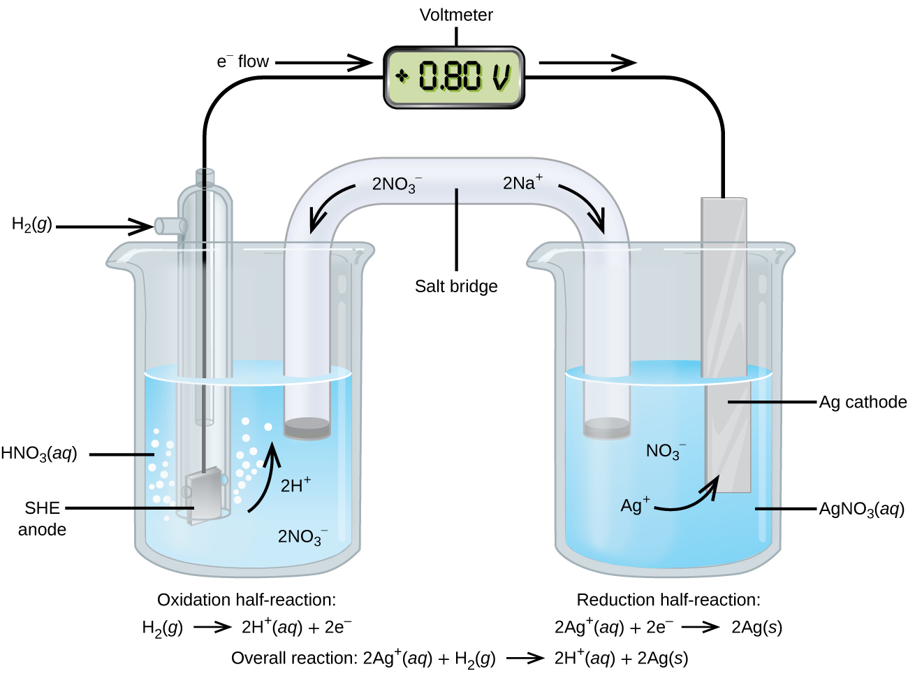
Using the SHE as a reference, other standard reduction potentials can be determined. Consider the cell shown in Figure 18.4c, where

[latex]\text{Pt}(s){\mid}\text{H}_2(\text{g, 1 atm}){\mid}\text{H}^{+}(\text{aq, 1 M}){\parallel}\text{Ag}^{+}(\text{aq, 1 M}){\mid}\text{Ag}(s)[/latex]

Electrons flow from left to right, and the reactions are

[latex]\begin{array}{lr @{{}\longrightarrow{}} l} \text{anode (oxidation):} & \text{H}_2(g) & \longrightarrow 2\text{ H}^{+}(aq)\;+\;2\text{ e}^{-} \\[0.5em] \text{cathode (reduction):} & 2\text{ Ag}^{+}(aq)\;+\;2\text{ e}^{-} & \longrightarrow 2\text{ Ag}(s) \\[0.5em] \hline \\[-0.25em] \text{overall:} & 2\text{ Ag}^{+}(aq)\;+\;\text{H}_2(g) & \longrightarrow 2\text{ H}^{+}(aq)\;+\;2\text{ Ag}(s) \end{array}[/latex]

The standard reduction potential can be determined by subtracting the standard reduction potential for the reaction occurring at the anode from the standard reduction potential for the reaction occurring at the cathode. The minus sign is needed because oxidation is the reverse of reduction.

[latex]E_{\text{cell}}^{\circ} = E_{\text{cathode}}^{\circ}\;-\;E_{\text{anode}}^{\circ}[/latex]
[latex]+0.80\;\text{V} = E_{\text{Ag}^{+}/\text{Ag}}^{\circ}\;-\;E_{\text{H}^{+}/\text{H}_2}^{\circ} = E_{\text{Ag}^{+}/\text{Ag}}^{\circ}\;-\;0 = E_{\text{Ag}^{+}/\text{Ag}}^{\circ}[/latex]

It is important to note that the potential is not doubled for the cathode reaction.


This figure contains a diagram of an electrochemical cell. Two beakers are shown. Each is just over half full. The beaker on the left contains a clear, colorless solution which is labeled “H N O subscript 3 ( a q ).” The beaker on the right contains a clear, colorless solution which is labeled “A g N O subscript 3 ( a q ).” A glass tube in the shape of an inverted U connects the two beakers at the center of the diagram and is labeled “Salt bridge.” The tube contents are colorless. The ends of the tubes are beneath the surface of the solutions in the beakers and a small grey plug is present at each end of the tube. The label “2 N a superscript plus” appears on the upper right portion of the tube. A curved arrow extends from this label down and to the right. The label “2 N O subscript 3 superscript negative” appears on the upper left portion of the tube. A curved arrow extends from this label down and to the left. The beaker on the left has a glass tube partially submerged in the liquid. Bubbles are rising from the grey square, labeled “SHE anode” at the bottom of the tube. A curved arrow points up to the right. The labels “2 H superscript plus” and “2 N O subscript 3 superscript negative” appear on the liquid in the beaker. A black wire extends from the grey square up the interior of the tube through a small port at the top to a rectangle with a digital readout of “positive 0.80 V” which is labeled “Voltmeter.” A second small port extends out the top of the tube to the left. An arrow points to the port opening from the left. The base of this arrow is labeled “H subscript 2 ( g ).” The beaker on the right has a silver strip that is labeled “A g cathode.” A wire extends from the top of this strip to the voltmeter. An arrow points toward the voltmeter from the left which is labeled “e superscript negative flow.” Similarly, an arrow points away from the voltmeter to the right. The solution in the beaker on the right has the labels “N O subscript 3 superscript negative” and “A g superscript plus” on the solution. A curved arrow extends from the A g superscript plus label to the A g cathode. Below the left beaker at the bottom of the diagram is the label “Oxidation half-reaction: H subscript 2 ( g ) right pointing arrow 2 H superscript plus ( a q ) plus 2 e superscript negative.” Below the right beaker at the bottom of the diagram is the label “Reduction half-reaction: 2 A g superscript plus ( a q ) right pointing arrow 2 A g ( s ).”
Figure 18.4c: A galvanic cell can be used to determine the standard reduction potential of Ag+. The SHE on the left is the anode and assigned a standard reduction potential of zero in Chemistry (OpenStax), CC BY 4.0).

The SHE is rather dangerous and rarely used in the laboratory. Its main significance is that it established the zero for standard reduction potentials. Once determined, standard reduction potentials can be used to determine the standard cell potential, [latex]E_{\text{cell}}^{\circ}[/latex], for any cell. For example, for the cell shown in Figure 18.3b in 18.3 – Galvanic Cells.

[latex]\text{Cu}(s){\mid}\text{Cu}^{2+}(\text{aq, 1 M}){\parallel}\text{Ag}^{+}(\text{aq, 1 M}){\mid}\text{Ag}(s)[/latex]

[latex]\begin{array}{lr @{{}\longrightarrow{}} l} \text{anode (oxidation):} & \text{Cu}(s) & \longrightarrow\text{Cu}^{2+}(aq)\;+\;2\text{ e}^{-} \\[0.5em] \text{cathode (reduction):} & 2\text{ Ag}^{+}(aq)\;+\;2\text{ e}^{-} & \longrightarrow 2\text{ Ag}(s) \\[0.5em] \hline \\[-0.25em] \text{overall:} & \text{Cu}(s)\;+\;2\text{ Ag}^{+}(aq) & \longrightarrow\text{Cu}^{2+}(aq)\;+\;2\text{ Ag}(s) \\[0.5em]\end{array}\\[0.5em][/latex]

[latex]E_{\text{cell}}^{\circ} = E_{\text{cathode}}^{\circ}\;-\;E_{\text{anode}}^{\circ} = E_{\text{Ag}^{+}/\text{Ag}}^{\circ}\;-\;E_{\text{Cu}^{2+}/\text{Cu}}^{\circ} = 0.80\;\text{V}\;-\;0.34\;\text{V} = 0.46\;\text{V}[/latex]

Again, note that when calculating [latex]E_{\text{cell}}^{\circ}[/latex], standard reduction potentials always remain the same even when a half-reaction is multiplied by a factor. Standard reduction potentials for selected reduction reactions are shown in Table 18.4a. A more complete list is provided in Appendix M.

Tables like this make it possible to determine the standard cell potential for many oxidation-reduction reactions.

Table 18.4a: Selected Standard Reduction Potentials at 25 °C
Half-Reaction E° (V)
F2(g) + 2 e → 2 F(aq) +2.866
PbO2(s) + SO42-(aq) + 4 H+(aq) + 2 e → PbSO4(s) + 2 H2O(l) +1.69
MnO4(aq) + 8 H+(aq) + 5 e → Mn2+(aq) + 4 H2O(l) +1.507
Au3+(aq) + 3 e → Au(s) +1.498
Cl2(g) + 2 e → 2 Cl(aq) +1.35827
O2(g) + 4 H+(aq) + 4 e → 2 H2O(l) +1.229
Pt2+(aq) + 2 e → Pt(s) +1.20
Br2(aq) + 2 e → 2 Br(aq) +1.0873
Ag+(aq) + e → Ag(s) +0.7996
Hg22+(aq) + 2 e → 2 Hg(l) +0.7973
Fe3+(aq) + e → Fe2+(aq) +0.771
MnO4(aq) + 2 H2O(l) + 3 e → MnO2(s) + 4 OH(aq) +0.558
I2(s) + 2 e → 2 I(aq) +0.5355
NiO2(s) +2 H2O(l) + 2 e → Ni(OH)2(s) + 2 OH(aq) +0.49
Cu2+(aq) + 2 e → Cu(s) +0.337
Hg2Cl2(s) + 2 e → 2 Hg(l) + 2 Cl(aq) +0.26808
AgCl(s) + 2 e → Ag(s) + Cl(aq) +0.22233
Sn4+(aq) + 2 e → Sn2+(aq) +0.151
2 H+(aq) + 2 e → H2(g) 0.00
Pb2+(aq) + 2 e → Pb(s) −0.126
Sn2+(aq) + 2 e → Sn(s) −0.1262
Ni2+(aq) + 2 e → Ni(s) −0.257
Co2+(aq) + 2 e → Co(s) −0.28
PbSO4(s) + 2 e → Pb(s) + SO42-(aq) −0.3505
Cd2+(aq) + 2 e → Cd(s) −0.4030
Fe2+(aq) + 2 e → Fe(s) −0.447
Cr3+(aq) + 3 e → Cr(s) −0.744
Mn2+(aq) + 2 e → Mn(s) −1.185
Zn(OH)2(s) + 2e → Zn(s) + 2 OH(aq) −1.245
Zn2+(aq) +  2 e → Zn(s) −0.7618
Al3+(aq) + 3 e→ Al(s) −1.662
Mg2+(aq) + 2 e → Mg(s) −2.372
Na+(aq) + e → Na(s) −2.71
Ca2+(aq) + 2 e → Ca(s) −2.868
Ba2+(aq) + 2 e → Ba(s) −2.912
K+(aq) + e → K(s) −2.931
Li+(aq) + e → Li(s) −3.04

Example 18.4a

Cell Potentials from Standard Reduction Potentials

What is the standard cell potential for a galvanic cell that consists of Au3+/Au and Ni2+/Ni half-cells? Identify the oxidizing and reducing agents.

Solution

Using Table 18.4a, the reactions involved in the galvanic cell, both written as reductions, are

[latex]\text{Au}^{3+}(aq)\;+\;3\text{ e}^{-}\;{\longrightarrow}\;\text{Au}(s)\;\;\;\;\;\;\;E_{\text{Au}^{3+}/\text{Au}}^{\circ} = +1.498\;\text{V}[/latex]
[latex]\text{Ni}^{2+}(aq)\;+\;2\text{ e}^{-}\;{\longrightarrow}\;\text{Ni}(s)\;\;\;\;\;\;\;E_{\text{Ni}^{2+}/\text{Ni}}^{\circ} = -0.257\;\text{V}[/latex]

Galvanic cells have positive cell potentials, and all the reduction reactions are reversible. The reaction at the anode will be the half-reaction with the smaller or more negative standard reduction potential. Reversing the reaction at the anode (to show the oxidation) but not its standard reduction potential gives:

[latex]{\scriptsize \begin{array}{lr @{{}\longrightarrow{}} ll} \text{Anode (oxidation):} & \text{Ni}(s) & \longrightarrow\text{Ni}^{2+}(aq)\;+\;2\text{ e}^{-} & E_{\text{anode}}^{\circ} = E_{\text{Ni}^{2+}/\text{Ni}}^{\circ} = -0.257\;\text{V} \\[0.5em] \text{Cathode (reduction):} & \text{Au}^{3+}(aq)\;+\;3\text{ e}^{-} & \longrightarrow \text{Au}(s) & E_{\text{cathode}}^{\circ} = E_{\text{Au}^{3+}/\text{Au}}^{\circ} = +1.498\;\text{V} \end{array} \scriptsize}[/latex]

The least common factor is six, so the overall reaction is

[latex]3\text{ Ni}(s)\;+\;2\text{ Au}^{3+}(aq)\;{\longrightarrow}\;3\text{ Ni}^{2+}(aq)\;+\;2\text{ Au}(s)[/latex]

The reduction potentials are not scaled by the stoichiometric coefficients when calculating the cell potential, and the unmodified standard reduction potentials must be used.

[latex]E_{\text{cell}}^{\circ} = E_{\text{cathode}}^{\circ}\;-\;E_{\text{anode}}^{\circ} = 1.498\;\text{V}\;-\;(-0.257\;\text{V}) = 1.755\;\text{V}[/latex]

From the half-reactions, Ni is oxidized, so it is the reducing agent, and Au3+ is reduced, so it is the oxidizing agent.

Exercise 18.4a

A galvanic cell consists of a Mg electrode in 1 M Mg(NO3)2 solution and a Ag electrode in 1 M AgNO3 solution. Calculate the standard cell potential at 25 °C.

Check Your Answer[1]

Key Equations

  • [latex]E_{\text{cell}}^{\circ} = E_{\text{cathode}}^{\circ}\;-\;E_{\text{anode}}^{\circ}[/latex]

Attribution & References

Except where otherwise noted, this page is adapted by David Wegman from “17.3 Standard Reduction Potentials” In General Chemistry 1 & 2 by Rice University, a derivative of Chemistry (Open Stax) by Paul Flowers, Klaus Theopold, Richard Langley & William R. Robinson and is licensed under CC BY 4.0. ​Access for free at Chemistry (OpenStax)​.


  1. [latex]{\scriptsize \text{Mg}(s)\;+\;2\text{ Ag}^{+}(aq)\;{\longrightarrow}\;\text{Mg}^{2+}(aq)\;+\;2\text{ Ag}(s)\;\;\;\;\;\;\;E_{\text{cell}}^{\circ} = 0.7996\;\text{V}\;-\;(-2.372\;\text{V}) = 3.172\;\text{V} \scriptsize}[/latex]
definition

License

Icon for the Creative Commons Attribution 4.0 International License

Enhanced Introductory College Chemistry Copyright © 2023 by Gregory Anderson; Caryn Fahey; Jackie MacDonald; Adrienne Richards; Samantha Sullivan Sauer; J.R. van Haarlem; and David Wegman is licensed under a Creative Commons Attribution 4.0 International License, except where otherwise noted.

Share This Book