18.3 Galvanic Cells
Learning Objectives
- Use cell notation to describe galvanic cells
- Describe the basic components of galvanic cells
Galvanic cells, also known as voltaic cells, are electrochemical cells in which spontaneous oxidation-reduction reactions produce electrical energy. In writing the equations, it is often convenient to separate the oxidation-reduction reactions into half-reactions to facilitate balancing the overall equation and to emphasize the actual chemical transformations.
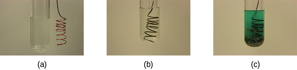
Consider what happens when a clean piece of copper metal is placed in a solution of silver nitrate (Figure 18.3a). As soon as the copper metal is added, silver metal begins to form and copper ions pass into the solution. The blue colour of the solution on the far right indicates the presence of copper ions. The reaction may be split into its two half-reactions. Half-reactions separate the oxidation from the reduction, so each can be considered individually.
[latex]\begin{array}{lr @{{}\longrightarrow{}} l} \text{oxidation:} & \text{Cu}(s) & \longrightarrow \text{Cu}^{2+}(aq)\;+\;2\text{ e}^{-} \\[0.5em] \text{reduction:} & 2\;\times\;[\text{Ag}^{+}(aq)\;+\;\text{e}^{-} & \longrightarrow \text{Ag}(s)]\;\;\;\;\;\;\;\text{or}\;\;\;\;\;\;\;2\text{ Ag}^{+}(aq)\;+\;2\text{ e}^{-}\;{\longrightarrow}\;\text{Ag}(s) \\[0.5em] \hline \\[-0.25em] \text{overall:} & 2\text{ Ag}^{+}(aq)\;+\;\text{Cu}(s) & \longrightarrow 2\text{ Ag}(s)\;+\;\text{Cu}^{2+}(aq) \end{array}[/latex]
The equation for the reduction half-reaction had to be doubled so the number electrons “gained” in the reduction half-reaction equaled the number of electrons “lost” in the oxidation half-reaction.
Galvanic or voltaic cells involve spontaneous electrochemical reactions in which the half-reactions are separated (Figure 18.3b) so that current can flow through an external wire. The beaker on the left side of the figure is called a half-cell, and contains a 1 M solution of copper(II) nitrate [Cu(NO3)2] with a piece of copper metal partially submerged in the solution. The copper metal is an electrode. The copper is undergoing oxidation; therefore, the copper electrode is the anode. The anode is connected to a voltmeter with a wire and the other terminal of the voltmeter is connected to a silver electrode by a wire. The silver is undergoing reduction; therefore, the silver electrode is the cathode. The half-cell on the right side of the figure consists of the silver electrode in a 1 M solution of silver nitrate (AgNO3). At this point, no current flows—that is, no significant movement of electrons through the wire occurs because the circuit is open. The circuit is closed using a salt bridge, which transmits the current with moving ions. The salt bridge consists of a concentrated, nonreactive, electrolyte solution such as the sodium nitrate (NaNO3) solution used in this example. As electrons flow from left to right through the electrode and wire, nitrate ions (anions) pass through the porous plug on the left into the copper(II) nitrate solution. This keeps the beaker on the left electrically neutral by neutralizing the charge on the copper(II) ions that are produced in the solution as the copper metal is oxidized. At the same time, the nitrate ions are moving to the left, sodium ions (cations) move to the right, through the porous plug, and into the silver nitrate solution on the right. These added cations “replace” the silver ions that are removed from the solution as they were reduced to silver metal, keeping the beaker on the right electrically neutral. Without the salt bridge, the compartments would not remain electrically neutral and no significant current would flow. However, if the two compartments are in direct contact, a salt bridge is not necessary. The instant the circuit is completed, the voltmeter reads +0.46 V, this is called the cell potential. The cell potential is created when the two dissimilar metals are connected, and is a measure of the energy per unit charge available from the oxidation-reduction reaction. The volt is the derived SI unit for electrical potential
In this equation C is the charge in coulombs. Note that volts must be multiplied by the charge in coulombs (C) to obtain the energy in joules (J).
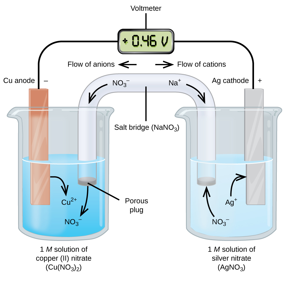
When the electrochemical cell is constructed in this fashion, a positive cell potential indicates a spontaneous reaction and that the electrons are flowing from the left to the right. There is a lot going on in Figure 18.3b, so it is useful to summarize things for this system:
- Electrons flow from the anode to the cathode: left to right in the standard galvanic cell in the figure.
- The electrode in the left half-cell is the anode because oxidation occurs here. The name refers to the flow of anions in the salt bridge toward it.
- The electrode in the right half-cell is the cathode because reduction occurs here. The name refers to the flow of cations in the salt bridge toward it.
- Oxidation occurs at the anode (the left half-cell in the figure).
- Reduction occurs at the cathode (the right half-cell in the figure).
- The cell potential, +0.46 V, in this case, results from the inherent differences in the nature of the materials used to make the two half-cells.
- The salt bridge must be present to close (complete) the circuit and both an oxidation and reduction must occur for current to flow.
There are many possible galvanic cells, so a shorthand notation is usually used to describe them. The cell notation (sometimes called a cell diagram) provides information about the various species involved in the reaction. This notation also works for other types of cells. A vertical line, │, denotes a phase boundary and a double line, ‖, the salt bridge. Information about the anode is written to the left, followed by the anode solution, then the salt bridge (when present), then the cathode solution, and, finally, information about the cathode to the right. The cell notation for the galvanic cell in Figure 18.3b is then:
Note that spectator ions are not included and that the simplest form of each half-reaction was used. When known, the initial concentrations of the various ions are usually included.
One of the simplest cells is the Daniell cell. It is possible to construct this battery by placing a copper electrode at the bottom of a jar and covering the metal with a copper sulfate solution. A zinc sulfate solution is floated on top of the copper sulfate solution; then a zinc electrode is placed in the zinc sulfate solution. Connecting the copper electrode to the zinc electrode allows an electric current to flow. This is an example of a cell without a salt bridge, and ions may flow across the interface between the two solutions.
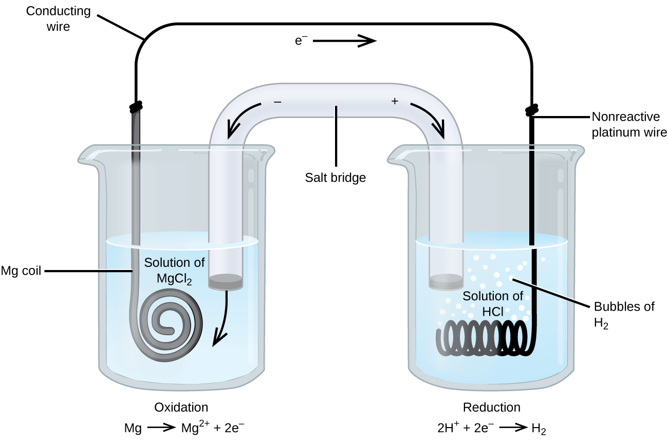
Some oxidation-reduction reactions involve species that are poor conductors of electricity, and so an electrode is used that does not participate in the reactions. Frequently, the electrode is platinum, gold, or graphite, all of which are inert to many chemical reactions. One such system is shown in Figure 18.3c. Magnesium undergoes oxidation at the anode on the left in the figure and hydrogen ions undergo reduction at the cathode on the right. The reaction may be summarized as
[latex]\begin{array}{lr @{{}\longrightarrow{}} l} \text{oxidation:} & \text{Mg}(s) & \longrightarrow \text{Mg}^{2+}(aq)\;+\;2\text{ e}^{-} \\[0.5em] \text{reduction:} & 2\text{ H}^{+}(aq)\;+\;2\text{ e}^{-} & \longrightarrow \text{H}_2(g) \\[0.5em] \hline \\[-0.25em] \text{overall:} & \text{Mg}(s)\;+\;2\text{ H}^{+}(aq) & \longrightarrow \text{Mg}^{2+}(aq)\;+\;\text{H}_2(g) \end{array}[/latex]
The cell used an inert platinum wire for the cathode, so the cell notation is
The magnesium electrode is an active electrode because it participates in the oxidation-reduction reaction. Inert electrodes, like the platinum electrode in Figure 18.3c, do not participate in the oxidation-reduction reaction and are present so that current can flow through the cell. Platinum or gold generally make good inert electrodes because they are chemically unreactive.
Example 18.3a
Using Cell Notation
Consider a galvanic cell consisting of
Write the oxidation and reduction half-reactions and write the reaction using cell notation. Which reaction occurs at the anode? The cathode?
Solution
By inspection, Cr is oxidized when three electrons are lost to form Cr3+, and Cu2+ is reduced as it gains two electrons to form Cu. Balancing the charge gives
[latex]\begin{array}{lr @{{}\longrightarrow{}} l} \text{oxidation:} & 2\text{ Cr}(s) & \longrightarrow 2\text{ Cr}^{3+}(aq)\;+\;6\text{ e}^{-} \\[0.5em] \text{reduction:} & 3\text{ Cu}^{2+}(aq)\;+\;6\text{ e}^{-} & \longrightarrow 3\text{ Cu}(s) \\[0.5em] \hline \\[-0.25em] \text{overall:} & 2\text{ Cr}(s)\;+\;3\text{ Cu}^{2+}(aq) & \longrightarrow 2\text{ Cr}^{3+}(aq)\;+\;3\text{ Cu}(s) \end{array}[/latex]
Cell notation uses the simplest form of each of the equations, and starts with the reaction at the anode. No concentrations were specified so:
[latex]\text{Cr}(s){\mid}\text{Cr}^{3+}(aq){\parallel}\text{Cu}^{2+}(aq){\mid}\text{Cu}(s)[/latex]. Oxidation occurs at the anode and reduction at the cathode.
Example 18.3b
Using Cell Notation
Consider a galvanic cell consisting of
[latex]5\text{ Fe}^{2+}(aq)\;+\;\text{MnO}_4^{\;\;-}(aq)\;+\;8\text{ H}^{+}(aq)\;{\longrightarrow}\;5\text{ Fe}^{3+}(aq)\;+\;\text{Mn}^{2+}(aq)\;+\;4\text{ H}_2\text{O}(l)[/latex]
Write the oxidation and reduction half-reactions and write the reaction using cell notation. Which reaction occurs at the anode? The cathode?
Solution
By inspection, Fe2+ undergoes oxidation when one electron is lost to form Fe3+, and MnO4− is reduced as it gains five electrons to form Mn2+. Balancing the charge gives
[latex]\begin{array}{lr @{{}\longrightarrow{}} l} \text{oxidation:} & 5\;\times\;[\text{Fe}^{2+}(aq) & \longrightarrow \text{Fe}^{3+}(aq)\;+\;\text{e}^{-}] \\[0.5em] \text{reduction:} & \text{MnO}_4^{\;\;-}(aq)\;+\;8\text{ H}^{+}(aq)\;+\;5\text{ e}^{-} & \longrightarrow \text{Mn}^{2+}(aq)\;+\;4\text{ H}_2\text{O}(l) \\[0.5em] \hline \\[-0.25em] \text{overall:} & 5\text{ Fe}^{2+}(aq)\;+\;\text{MnO}_4^{\;\;-}(aq)\;+\;8\text{ H}^{+}(aq) & \longrightarrow 5\text{ Fe}^{3+}(aq)\;+\;\text{Mn}^{2+}(aq)\;+\;4\text{ H}_2\text{O}(l) \end{array}[/latex]
Cell notation uses the simplest form of each of the equations, and starts with the reaction at the anode. It is necessary to use an inert electrode, such as platinum, because there is no metal present to conduct the electrons from the anode to the cathode. No concentrations were specified so: [latex]\text{Pt}(s){\mid}\text{Fe}^{2+}(aq)\text{,}\;\text{Fe}^{3+}(aq){\parallel}\text{MnO}_4^{\;\;-}(aq)\text{,}\;\text{H}^{+}(aq)\text{,}\;\text{Mn}^{2+}(aq){\mid}\text{Pt}(s)[/latex].
Oxidation occurs at the anode and reduction at the cathode.
Exercise 18.3a
Use cell notation to describe the galvanic cell where copper(II) ions are reduced to copper metal and zinc metal is oxidized to zinc ions.
Check Your Answer[1]
Links to Interactive Learning Tools
Explore Galvanic Cells from the Physics Classroom.
Key Equations
[latex]\text{volt} = V = \frac{\text{J}}{\text{C}}[/latex]
Attribution & References
Except where otherwise noted, this page is adapted by David Wegman from “17.2 Galvanic Cells” In General Chemistry 1 & 2 by Rice University, a derivative of Chemistry (Open Stax) by Paul Flowers, Klaus Theopold, Richard Langley & William R. Robinson and is licensed under CC BY 4.0. Access for free at Chemistry (OpenStax).
-
From the information given in the problem:
[latex]\begin{array}{lr @{{}\longrightarrow{}} l} \text{anode (oxidation):} & \text{Zn}(s) & \longrightarrow \text{Zn}^{2+}(aq)\;+\;2\text{ e}^{-} \\[0.5em] \text{cathode (reduction):} & \text{Cu}^{2+}(aq)\;+\;2\text{ e}^{-} & \longrightarrow \text{Cu}(s) \\[0.5em] \hline \\[-0.25em] \text{overall:} & \text{Zn}(s)\;+\;\text{Cu}^{2+}(aq) & \longrightarrow \text{Zn}^{2+}(aq)\;+\;\text{Cu}(s) \end{array}[/latex]Using cell notation: [latex]\text{Zn}(s){\mid}\text{Zn}^{2+}(aq){\parallel}\text{Cu}^{2+}(aq){\mid}\text{Cu}(s)[/latex].↵
electrochemical cell that involves a spontaneous oxidation-reduction reaction; electrochemical cells with positive cell potentials; also called a voltaic cell
another name for a galvanic cell
electrode in an electrochemical cell at which oxidation occurs; information about the anode is recorded on the left side of the salt bridge in cell notation
electrode in an electrochemical cell at which reduction occurs; information about the cathode is recorded on the right side of the salt bridge in cell notation
created when two dissimilar metals are connected together and is a measure of the energy per unit charge available from the oxidation-reduction reaction
shorthand way to represent the reactions in an electrochemical cell
electrode that participates in the oxidation-reduction reaction of an electrochemical cell; the mass of an active electrode changes during the oxidation-reduction reaction
electrode that allows current to flow, but that does not otherwise participate in the oxidation-reduction reaction in an electrochemical cell; the mass of an inert electrode does not change during the oxidation-reduction reaction; inert electrodes are often made of platinum or gold because these metals are chemically unreactive.
