Instrument Devices – Temperature Measuring Devices
Include the following:
- Resistance measuring devices
- Thermocouples
- Radiation measuring devices
Resistance Measuring Devices
Resistance Temperature Detector
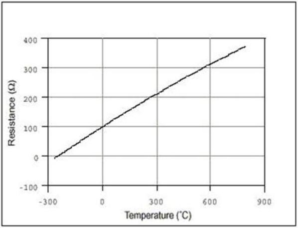
Also known as RTDs operate on the principle of changes in the electrical resistance of pure metals. Resistance measuring devices have a linear positive change in resistance with temperature.
Video: Temperature Sensor Technology Demo
Watch “Temperature Sensor Technology Demo featuring Peter Welander and Moore Industries WORM” [7:59].
The image below depicts a few examples of how RTDs can be physically manufactured. The wire produces a varying amount of resistance, based on the temperature that it is exposed to.
Resistance measuring devices, such as resistance temperature detectors, utilize metals that exhibit specific behavior:
- When the temperature of these metals increases, their electrical resistance also increases.
- When the temperature decreases, the resistance decreases as well.
Metals in RTDs
Video: Temperature: RTD
Watch “Temperature: RTD (Resistance Temperature Detector)” [1:10].
Typical elements used for RTDs include:
- Nickel (ni)
- Copper (cu)
- Platinum (pt): by far the most common because of its wide temperature range, accuracy, and stability.
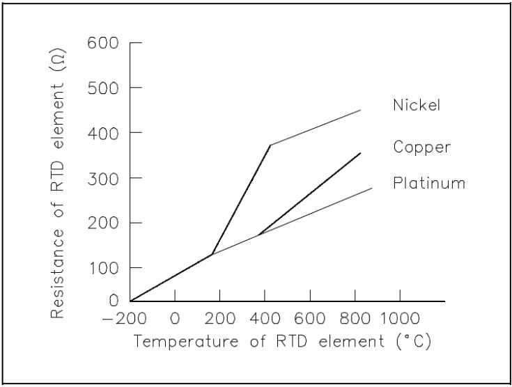
Electrical Resistance-Temperature Curves
RTD Metal Qualities
| Metal | Temperature coefficient of resistance,
Ω Ω °C at 0 °C Range 0 – 100 °C |
Melting point, °C | Useful Range, °C |
| Platinum | 0.00392 | 1 773 | -263 to 545 |
| Nickel | 0.0063 to 0.0066 | 1 455 | -190 to 310 |
| Copper | 0.00425 | 1 083 | -40 to 125 |
Metal qualities suitable for measuring temperature changes in a power plant include:
- The amount of resistance change is sufficiently large to be easily measured.
- The melting point of the metal is higher than the temperature range it is intended to monitor.
- The magnitude of the resistance change for a given temperature change is consistent and repeatable.
- The metals used in these devices are relatively simple to produce and cost-effective to use.
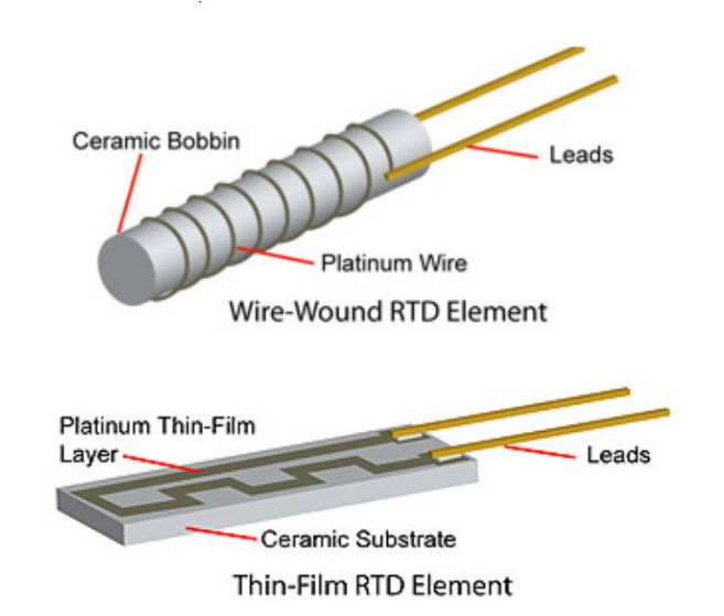
RTDs can be constructed using one of two methods:
- Wire-wound: This approach involves winding a thin wire into a coil configuration to create the RTD sensor.
- Thin-film element: In this method, a very thin layer of metal is deposited onto a plastic or ceramic substrate to form the RTD sensor. This approach is more prevalent than the wire-wound method.
Activity: Types of Resistance Temperature Detector Construction
Click the arrow to view the different types of resistance temperature detector construction.
Activity: Resistance Temperature Detector
Click the arrow to view resistance temperature detectors and the wells that receive them.
Advantages:
- Stable output for long periods of time.
- Ease of recalibration.
- Accurate readings over relatively narrow temperature spans.
- Wide operating range.
- Suitability for precision applications.
Disadvantages:
- Smaller overall temperature range.
- Higher initial cost.
- Less rugged in high-vibration environments.
- Rarely used above 660 °C.
- RTDs have a slower response time.
Activity: Explore the Different Methods of Using an RTD Input
Click the image hotspots to view the steps in the deflection method of using an RTD input.
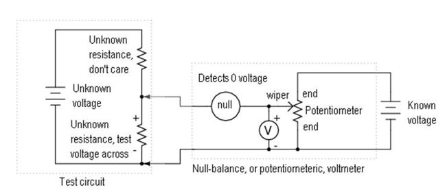
Click the image hotspots to view the steps in the null balance method of using an RTD input.
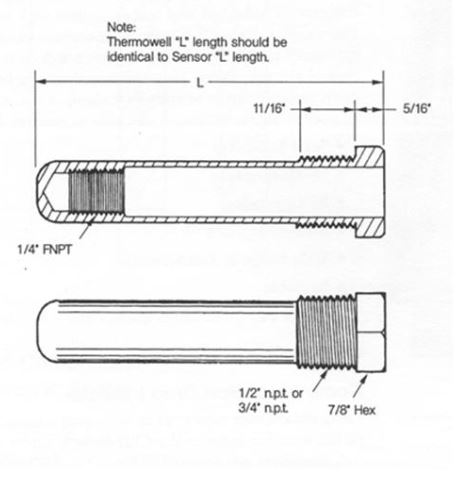
A resistance temperature detector is usually contained within a thermowell or a similar sheath that is inserted into a gas or liquid stream. The presence of Thermowell increases the probes response time to temperature variations making resistance devices slower to respond. The image below depicts a graphical representation of the “well” that the RTD inserts into. The well is placed into the process stream which allows the RTD to be removed without the process fluid coming out.
Click this link to visit Wisc-Online’s webpage and learn more about RTDs.
Thermal Resistor
A thermistor is a type of resistor whose resistance varies with temperature.
- Differs from resistance temperature detectors (RTD) in that the material used in a thermistor is generally a ceramic or polymer, while RTDs use pure metals.
- The resistance of a thermistor decreases with increasing temperature.
- RTDs are useful over larger temperature ranges, while thermistors typically achieve a higher precision within a limited temperature range -100°C to 400°C.
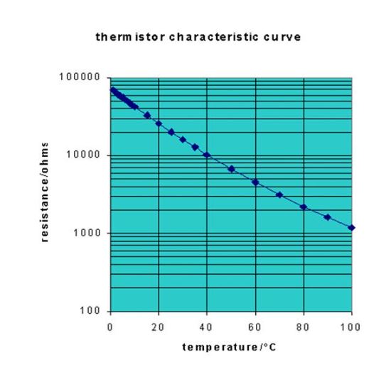
Thermistor characteristic curve Activity: Thermistor
Click the arrow to view the different configurations of Thermistors suitable to different operating environments, conditions, and size availabilities.
Advantages:
- Versatile: Thermistors can be molded into various shapes to conveniently fit the equipment they need to monitor.
- Due to their high resistance, the resistance of the lead wires is typically not a significant factor.
- Compact: Thermistors have a small and compact design, making them suitable for space-limited applications.
- Low cost: Thermistors are generally affordable, making them a cost-effective choice for temperature sensing.
- Reliable: Thermistors are known for their reliability and stability in temperature measurement.
- Accurate: Thermistors provide accurate temperature readings, ensuring precise monitoring and control.
Disadvantages:
- Non-linear relationship: The relationship between resistance and temperature in thermistors is not linear, which can make calibration and precise temperature measurements more challenging.
- Limited temperature range: Thermistors have a specific temperature range within which they operate accurately. Outside of this range, their performance may be compromised or unreliable.
Thermocouples
A thermocouple is a temperature-measuring sensor. It is composed of two dissimilar metals that are joined at one end. When this junction of two metals is heated or cooled, it generates a voltage. This voltage can then be correlated to the corresponding temperature. Typically, thermocouple junctions are housed within a thermowell.
Video: Thermocouples
Watch “Thermocouples” [3:24].
ISA types are used to specify commercially available thermocouples.
- Base-metal thermocouples, including Type E, J, K, and T, are commonly used and suitable for temperatures up to approximately 1000°C (1832°F).
- Noble-metal thermocouples, such as Type S, R, and B, are designed for higher temperature applications and can be used up to around 2000°C (3632°F).
Video: Thermocouple Tutorial
Watch “Thermocouple Tutorial” [9:29].
Types of Thermocouples
| Type | First Wire | Second Wire | Useful Range, °C |
| B | Platinum, 30 % Rhodium | Platinum, 6% Rhodium | 0 to 1860 |
| E | Nickel, 10% Chromium | Constantan (copper-nickel) | -180 to 980 |
| J | Iron | Constantan | -0 to 815 |
| K | Chromel (nickel-copper) | Alumel (nickel-aluminum) | -180 to 1260 |
| R | Platinum, 13% Rhodium | Platinum | -45 to 1650 |
| S | Platinum, 10% Rhodium | Platinum | -45 to 1760 |
| T | Copper | Constantan | -180 to 980 |
Activity: Thermocouples
Click the arrow to view the different thermocouple configurations.
Common Thermocouple Temperature Ranges
| Calibration | Temperature Ranges | Std. Limits of Error | Spec. Limits of Error |
| J | 0°C to 750°C
(32°F to 1382°F) |
Greater of 2.2°C or 0.75% | Greater of 1.1°C or 0.4% |
| K | -200°C to 1250°C
(-328°F to 2282°F) |
Greater of 2.2°C or 0.75% | Greater of 1.1°C or 0.4% |
| E | -200°C to 900°C
(-328°F to 1652°F) |
Greater of 1.7°C or 0.5% | Greater of 1.0°C or 0.4% |
| T | -250°C to 350°C
(-328°F to 662°F) |
Greater of 1.0°C or 0.75% | Greater of 0.5°C or 0.4% |
The thermocouple’s durability in challenging conditions is ensured by a stainless steel sheath and magnesium oxide insulation, resulting in improved responsiveness to fluctuations in temperature.
Activity: Sheathed Thermocouple
Click the arrow to view examples of sheathed thermocouples.
Advantages:
- Independent of external power supply, capable of generating a temperature signal.
- Provides a linear output corresponding to the temperature difference across the junction.
- Cost-effective and reliable for long-distance measurements where the instrument is far from the measurement point.
- Compact size and quick response to temperature changes, make them versatile for various applications.
Disadvantages:
- Potential for error with thermocouples that are placed in a location remote from the measuring circuit.
- The lead wires from the thermocouple to the measuring instrument must have similar properties to the actual thermocouple wires, or else a secondary thermocouple is established where the original thermocouple is connected to its lead. If a long wire is needed, it can be expensive to form it from the same metal as the thermocouple.
- They are generally made of a heavy gauge which makes their electrical connections more difficult
- Need to compensate for the resistance of the galvanometer coil which may also change as temperature changes.
Radiation Pyrometers
Pyrometer is any non-contacting device that intercepts and measures thermal radiation. This measure is used to determine temperature, often of the object’s surface.
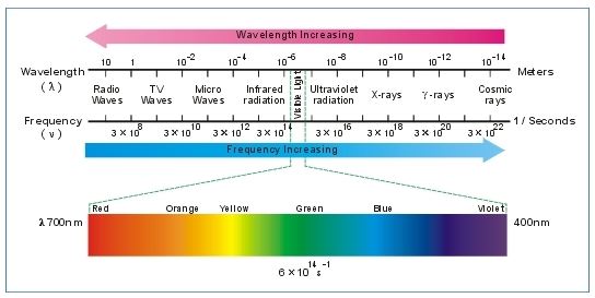
Infrared Radiation: also known as IR, similar to any light ray, is a form of electromagnetic radiation characterized by a lower frequency (or longer wavelength).
Pyrometers
Temperature sensing devices are designed to measure temperatures by directly interacting with the surface being measured. These devices, commonly found in portable and hand-held pyrometers, allow for convenient temperature assessment. Total-radiation pyrometers, specifically, are capable of detecting and responding to radiation across all wavelengths.
A disadvantage of pyrometers is that they are subject to errors due to heat energy contained in gases, water vapor, or particulate material located between the instrument and its measured surface.
Activity: Pyrometers
Click the image hotspots to view how a total-radiation pyrometer works.
Click the image hotspots to view how a total-radiation pyrometer with a mirror works.
Optical Pyrometers
Optical pyrometers are only responsive to specific wavelengths in the range of:
| Color | Temperature, °C |
| Incipient red | 500 – 550 |
| Dark red | 650 – 750 |
| Bright red | 850 – 950 |
| Yellowish red | 1050 – 1150 |
| Incipient white | 1250 – 1350 |
| White | 1450 – 1550 |
Activity: Optical Pyrometer
Click the image hotspots to view learn more about optical pyrometers.
Optical Pyrometer Filaments
Partial-Radiation Pyrometers
Similar to total-radiation pyrometers, they are sensitive to only a small band of wavelengths or to a single wavelength of radiated energy. They are particularly useful for high temperatures, in the range of 1063°C to 2000 °C.
Advantages:
- Quick response at high temperatures.
- Reduced errors due to fluctuations in emissivity.
- Little or no error due to intervening smoke or gases.
Disadvantage:
- Sensitivity to fluctuations in ambient temperature which often requires a water jacket for cooling the pyrometer.
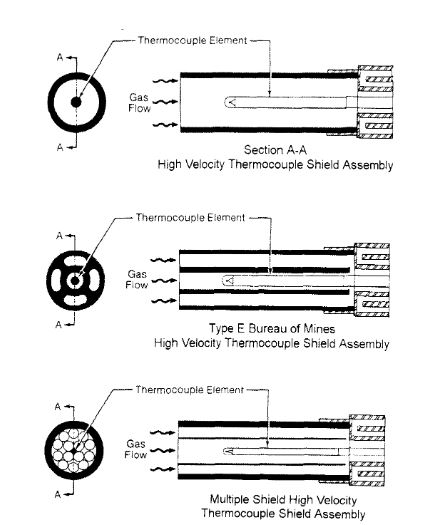
High-Velocity Thermocouples
Also known as HVT, High-velocity thermocouples are designed to measure furnace gas temperatures with reduced errors due to heat radiation effects. They are contained within a protective shield inserted into the gas stream. The shielding may be cooled by:
- A stream of compressed air is directed through it.
- A cooling water jacket on the portion that is external to the gas stream.
Temperature Transducers
Temperature transducers incorporate electrical output signals that are directed to indicating instruments and process control devices, even if they are located far away in a centralized control room. These transducers often incorporate electronic equipment that converts the output signal into a digital data stream, allowing process computers or controllers to directly utilize the information.
Portable Pyrometers
Used to:
- Confirm readings from field devices.
- Monitor areas or equipment experiencing temperature problems.
- Most accurate at temperatures from 0°C to above 538°C.
Optical Pyrometers
Especially useful at temperatures in excess of 816°C. Used to monitor a furnace’s internal temperatures.
Use and Placement of Temperature Measuring Devices
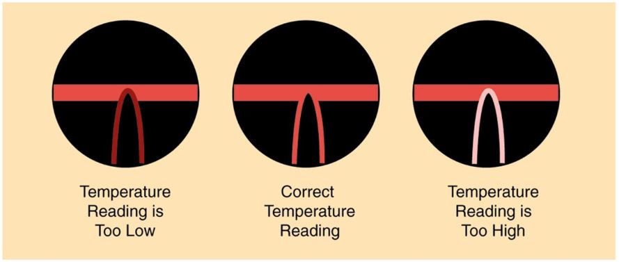
A temperature sensing device;
- Absorbs heat from the object or stream that it is measuring.
- Radiates heat to other bodies in the vicinity which are cooler, can cause errors in measurement.
- Are placed carefully to avoid inaccuracies due to their own radiation of heat.
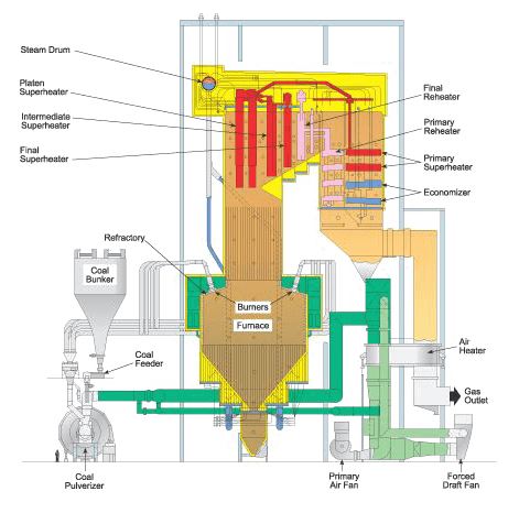
Temperature monitoring locations of the boiler in the illustration below include:
- Economizer feedwater inlet and outlet
- Steam drum
- Superheaters steam inlet and outlet
- Air preheater gas inlet and gas outlet
- Air preheater air inlet and air outlet
- Furnace gas side
- Primary air
- Reheaters inlet and outlet temperature
- Superheater gas temperature
The null balance method employs a variable voltage source, namely a potentiometer, to achieve voltage equilibrium in the measured system. The resistance of the potentiometer is adjusted at its wiper until the null detector indicates zero voltage across both circuits. As the two voltage sources are identical, measuring the adjustable source is equivalent to measuring the voltage across the test circuit.