Instrument Devices – Control Valves
Control Valves
Control valves are one of the final control elements used in various systems. They can take different forms, such as a damper, a variable speed drive for a feeder or other machine, or an agitator. In some cases, a control valve is specifically employed to provide either open or closed service, without the need for flow rate modulation or fluid pressure regulation. The final control element is coupled with an operator that positions it as the automatic control circuitry requires.
These valves are commonly coupled with an operator that positions them as the automatic control circuitry requires.
1. Linear types:
- Globe valves
- Slide valves
2. Rotary types:
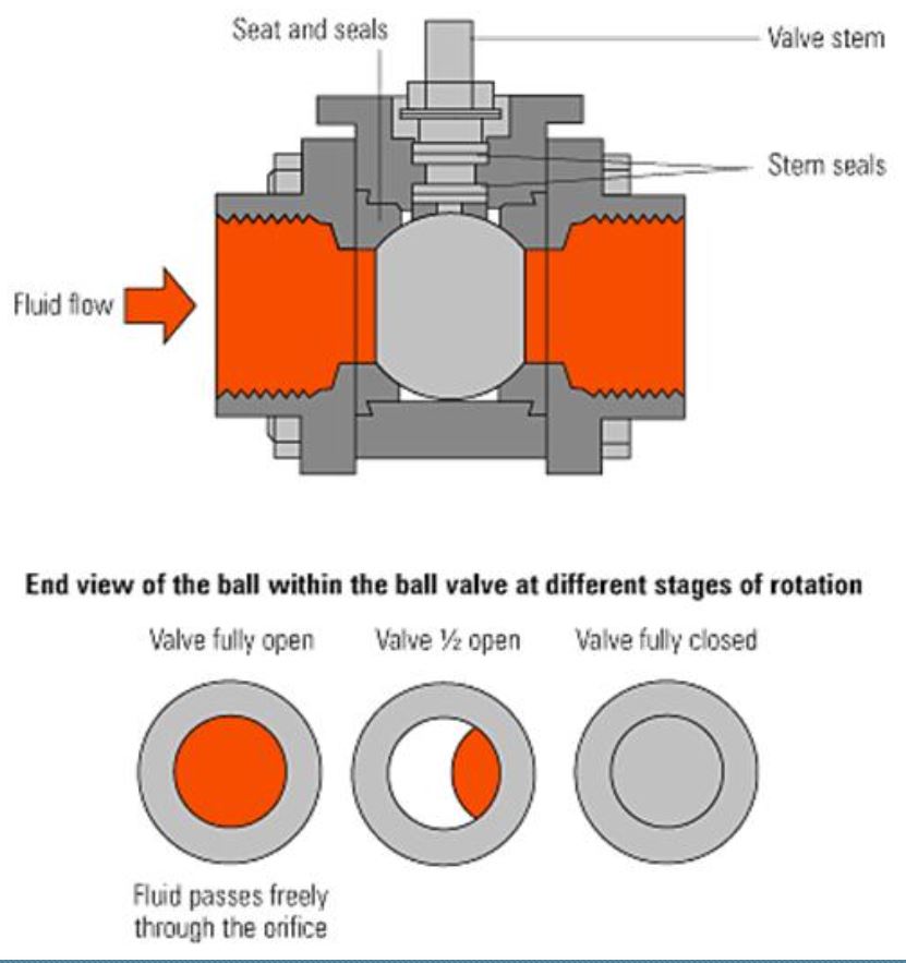
- Ball valves
- Butterfly valves
- Plug Valves
When it comes to valve selection, the first decision to make is between two-port and three-port valves. Two-port valves are primarily designed to throttle or restrict the fluid flow that passes through them. In contrast, three-port valves offer the capability to either mix different streams of liquid or divert the flow to different paths, providing greater flexibility in controlling fluid movement.
Two-port valves are commonly used in control applications due to their ability to effectively throttle the flow and their inherent capability to achieve a specific flow characteristic by correlating the valve opening with the flow rate. This makes them highly suitable for the precise control and regulation of fluid movement
Maximum differential pressure, the difference in pressure upstream, P1 and downstream, P2, against which a valve can close will depend upon the size and type of valve and the actuator operating it.
Force required from the actuator:
(A x ∆P) + Friction Allowance = F
Where:
A = Valve seating area (m2)
∆P = Differential pressure (kPa)
F = Closing force required (kN)
Globe Valves
Click the arrow to view the globe valves.
Disadvantage:
- Can be difficult to open and close when fluid pressure is applied to them.
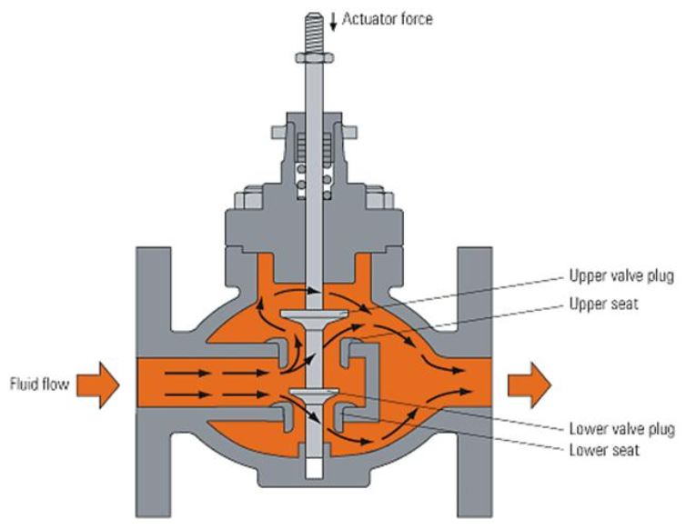
Double Seat Two-port Valve
The double-seat two-port valve has two valve plugs on a common spindle, with two valve seats. The valves have smaller seats and the forces are partially balanced.
Disadvantages:
- Manufacturing tolerances and varying coefficients of expansion can pose challenges.
- It can be difficult to ensure good shut-off tightness with many double-seat valves.
A globe valve must be installed correctly in the pipework, with flow entering the valve on its inlet side. An arrow on the valve body indicates the direction of flow through the valve.
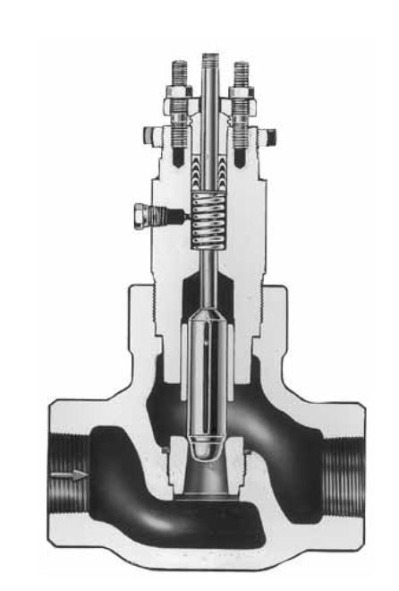
Balanced single-seat valves
For applications that require a tight shut-off, it is recommended to use a single-seat valve.
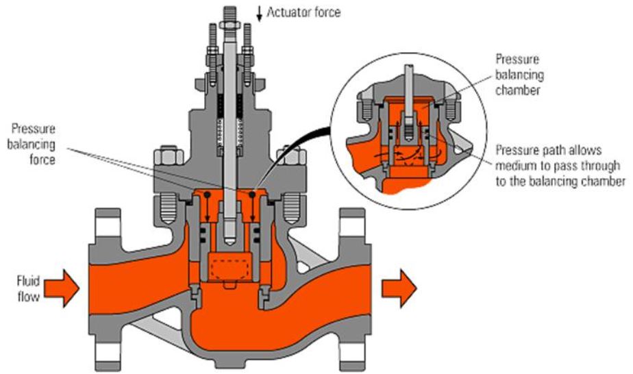
Piston-balanced Valve
In a piston-balanced valve, a portion of the upstream fluid pressure is transferred through internal pathways to a designated space located above the valve plug. This space functions as a pressure balancing chamber. The pressure present in this chamber exerts a downward force on the valve plug.
Balanced Single Seat Valve
Advantage:
- Can be designed for either downward or upward-opening movements.
- Accommodates valve operators that move in either direction.
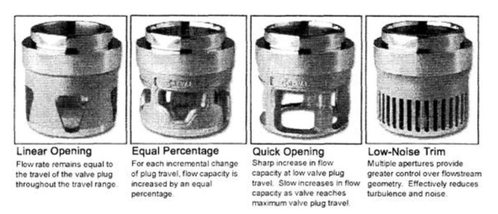
Activity: Globe Valve Characteristics
Click the arrows to learn more about globe valves.
In control valve applications, globe valves are commonly employed. These valves feature a plug-type disc, which consists of a long tapered shape that is particularly well-suited for throttling service.
Disadvantages:
- They produce a much greater loss of velocity head due to their internal resistance to flow
- This loss is many times the equivalent loss for a gate valve of the same size.
Slide Valves
Slide valves come in two different designs:
- Wedge gate type
- Parallel slide type
Slide valves give a tight shut-off and, when open, the pressure drop across them is very small. If automatic actuation is required, the parallel slide valve is usually chosen for either isolation or control.
Activity: Slide Valves
Click the arrow to learn more about the different types of slide valves.
Parallel Slide Valves
Large-size parallel slide valves are used in main steam and feedlines in the power and process industries to isolate sections of the plant. Small-bore parallel slides are also used for the control of ancillary steam and water services
Rotary-Type Valves
Rotary-type valves include:
- Plug valves
- Ball valves
- Butterfly Valves
These types of valves can easily be fitted with actuators.
Activity: Plug Valve
Click the arrows to view images of plug valves.
Activity: Butterfly Valve
Click the arrows to see images of butterfly valves.
Valve Actuator (Operator)
The purpose of the valve actuator (operator) is to accurately locate the valve plug in a position dictated by the control signal. The actuator accepts a signal from the control system and, in response, moves the valve to:
- A fully-open or fully-closed position
- A more open or a more closed position.
Valve operators have two major ways of providing actuation:
- Pneumatic
- Electric
Pneumatic actuators are available in two main forms:
- Piston actuators
2. Diaphragm actuators
Activity: Diaphragm Actuators
Click the arrows to learn more about diaphragm actuators.
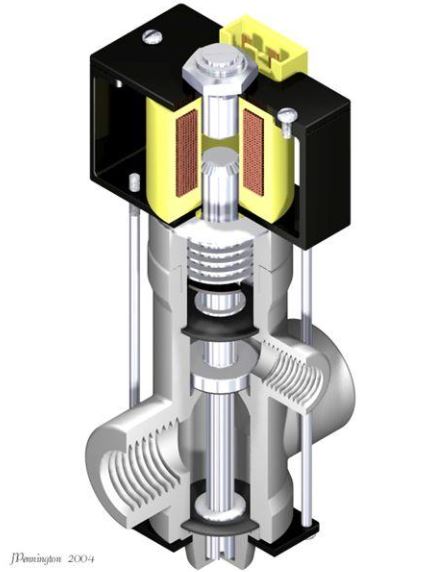
Solenoid Actuator
A solenoid actuator consists of an electrical conductor wound into a spiral or coil, enhancing the magnetic field it produces when energized. The coil turns are positioned in close proximity to each other, forming a compact arrangement with electrical insulation between them. These turns are radially arranged in multiple layers. In this configuration, adjacent turns of the coil carry current in the same direction, resulting in the generation of magnetic flux lines aligned in the same direction. Consequently, although the current flows through a single conductor, the magnetic field created resembles that of multiple conductors. In essence, the solenoid functions as a tubular electromagnet.
It operates through the interaction of a magnetic core, which can freely move within the coil. When an electrical current is applied to the coil, a force is generated along its length, propelling the core in a specific direction. To restore the core to its original position when the current is switched off, a spring can be utilized at the end of its travel. By alternately energizing and de-energizing the solenoid, the core moves back and forth axially. As a result, the solenoid serves as the operator for a valve, enabling it to open and close correspondingly as the electrical current is switched on and off.
Solenoid actuators may also be used for a pilot valve, which admits compressed air to a spring-loaded plunger or piston, which is the valve stem for the main valve.
- A small coil is sufficient to initiate the operation of a larger valve.
- More operating force is applied by the instrument air system.
Solenoid Valves
Restricted to smaller sizes, common in piping up to 30 mm.
Applications include the following:
- Sealing water supplies that are opened and closed as the equipment is started or stopped.
- Air or gas supplies to pneumatic control loops that see only intermittent operation.
- Pilot gas system vent valves.
Electric Actuator
Electric actuators use an electric motor with a range of voltage requirements:
- 230 Vac, 110 Vac, 24 Vac, and 24 Vdc.
There are two types of electrical actuator:
- Valve Motor Drive (VMD)
- Modulating
Valve Motor Drive
This basic version of the electric actuator has three states:
- Driving the valve open.
- Driving the valve closed.
- No movement.
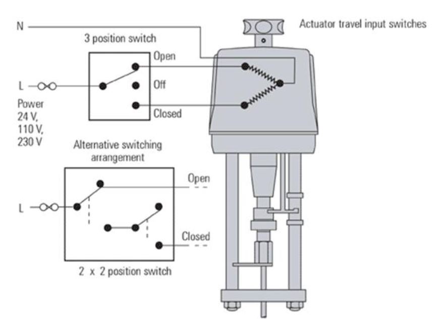
Electric Actuator
Limiting devices are fitted to protect the motors from over-travel damage.
Can be adjusted to limit valve strokes in oversized valves.
Torque switches, give a defined closing force on the valve seat, protecting the actuator in the case of valve stem seizure.
Electrodes stop and start the pump to maintain a level in the sump.
Limiting devices are commonly installed to safeguard motors against damage caused by over-travel. These devices can be adjusted to restrict valve strokes, particularly in the case of oversized valves. Another type of protective mechanism, torque switches, ensures a specific closing force on the valve seat. This serves as a crucial safeguard for the actuator, particularly in situations where valve stem seizure may occur.
Modulating
A positioning circuit may be included in the modulating actuator, which accepts an analog control signal. Actuator interprets this control signal, as the valve position between the limit switches. Actuator has a position sensor (usually a potentiometer), which feeds the actual valve position back to the positioning circuit. In this way, the actuator can be positioned along its stroke in proportion to the control signal.
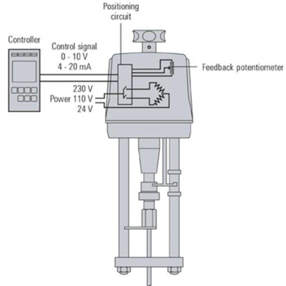
In pneumatic actuators, if there is a failure in the air supply or control signal, the valve will automatically close as a safety measure. On the other hand, electric actuators offer “spring reserve” versions that can be configured to either open or close the valve in the event of a power or control signal failure. Additionally, fail-safe functionality can be achieved through the use of battery power as a backup source.
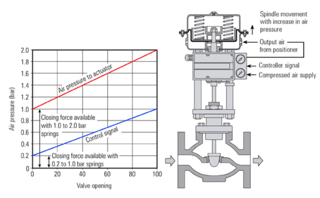
Valve Positioners
Valve positioner: relates the input signal and the valve position. It also provides output pressure to the actuator according to:
- Requirements of the valve
- Within the limitations of the maximum supply pressure.
A valve positioner is a device that serves as a high-gain proportional controller. It’s connected to the valve stem and monitors the position of the valve stem. The positioner compares the actual valve position with the desired setpoint received from the valve controller and makes necessary adjustments to correct any discrepancies or errors. The primary function of a positioner is to ensure that the valve moves precisely to the position dictated by the controller, thus guaranteeing optimal control and alignment between the valve’s actual position and the desired position.
Activity: Positioners
Click the arrows to view different diagrams of positioners.
In this arrangement, the control signal is applied to a bellows which positions a flapper in relation to a nozzle.
An increase in control signal pressure moves the flapper closer to the nozzle, causing the nozzle pressure to increase and the valve stem to move downward.
As the valve stem moves downward, the flapper moves away from the nozzle giving proportional action and stabilizing the valve movement.
If valve stern movement is prevented due to friction or other causes, the nozzle pressure continues to increase until the resisting force is overcome.
Positioners ensure that there is a linear relationship between the signal input pressure from the control system and the position of the control valve.
May be used as a signal amplifier or booster.
Accepts a low-pressure air control signal and, by using its own higher-pressure input, multiplies this to provide a higher-pressure output air signal to the actuator diaphragm.
Some positioners incorporate an electro-pneumatic converter so that an electrical input (typically 4 – 20 mA) can be used to control a pneumatic valve.
Some positioners can also act as basic controllers, accepting input from sensors.
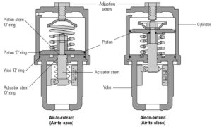
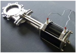
Power Cylinder Valve Operators
Power cylinder valve operators function by applying an air pressure signal to one side of a piston within a cylinder. On the opposite side, a spring is employed to counterbalance the force exerted. These cylinders are designed to be double acting, meaning that air pressure can be applied to either side of the piston to achieve positive motion in the desired direction. This allows for flexibility in controlling the movement of the valve, ensuring effective operation and positioning.
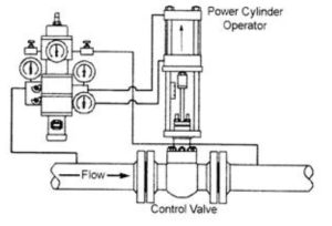
Power cylinder valve operators offer a significant output force, making them well-suited for applications involving large valves or valves that need to overcome fluid pressure. They are commonly used for operating ball valves and butterfly valves. These operators require minimal linear movement to fully open or close the valves and do not require regulation or throttling during operation. Similar to diaphragm operators, power cylinder operators are pneumatic devices that necessitate the use of a pneumatic positioner to achieve precise control and positioning.