Part 5: Wastewater Handleing Systems
Wastewater Handling Systems
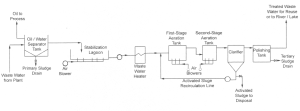
Wastewater Treatment
The purpose of wastewater systems can be summarized into 2 main points:
- Remove and properly dispose of the pollutants in the wastewater using the most practical and economic means
- Disinfect the wastewater before it is discharged to the receiving water
Activity: Exploring the Parts of A Wastewater System
Click on the accordions to learn about the different parts of a wastewater system.
Note: The numbers for each accordion tab correspond to the numbers on the diagram.
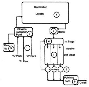
Preliminary Treatment
Preliminary Treatment generally includes: Bar screen, Fine particle sieving, Grit chamber, Pre-aeration, Grease well, and Scraping chamber.
Let’s take a look at a few of the preliminary treatment parts in more detail.
Screens and Shredders
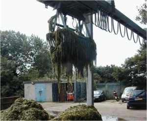
Bulky or fibrous material is either screened out, or shredded by using a bar screen or a rotating screen. A Bar screen is made up of vertical or horizontal steel bars.
Click the arrows to look at images of a Bar Screen.
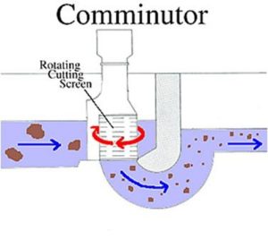
Communicator
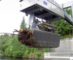
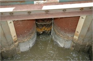
Rotating trash screen.
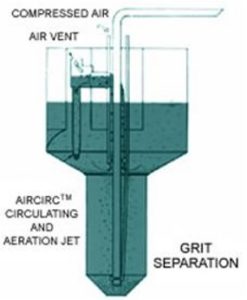
Grit Removal
Primary Treatment
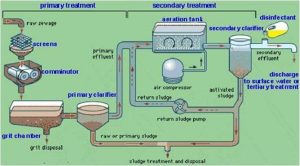
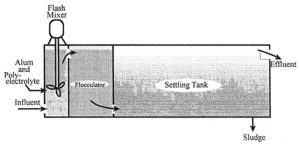
Primary treatment uses physical sedimentation or floatation to remove the majority of water-borne substances. Whenever coagulants are applied, colloidal substance can also be removed.
The primary treatment equipment consists of:
-
- Primary clarifier
- Flotation chamber
- Chemical coagulation
- Sedimentation
Let’s take a look at a few of the primary treatment equipment steps in closer detail.
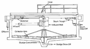
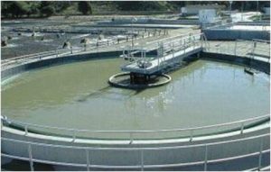
Primary Clarifier
During sedimentation gravity is used in the primary separation of suspended solids in wastewater. The typical detention time for a primary clarifier is two hours.
Floatation
An air/water mixture is introduced into the floatation tank with the activated sludge influent. The small air bubbles grab suspended particles and carry them to the top to be removed by a skimmer.
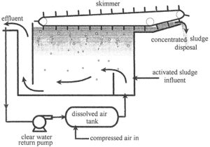 1 . In the Dissolved air tank– Clear effluent is returned to a dissolved air tank where it is pressurized with compressed air.
2. Air/water mixture is introduced into the floatation tank with the activated sludge influent.
3. The tiny bubbles that escape from the water attach to suspended material and float it to the top of the tank where the concentrated sludge is skimmed off by a slow moving skimmer.
4. The concentrated sludge is then sent to a dewatering process or directly to disposal.
Flocculation
Secondary Treatment
The Biological Removal of Solids can be carried out with the following processes:
-
-
- Activated sludge
- Rotating biological contactors
- Trickling filters
-
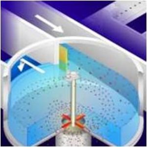
Secondary Clarifier
Activity: Secondary Clarifier
Click through the arrows to learn about the process of secondary clarification.

Activity: Secondary Clarifier (Continued)
Click through the arrows to learn about the process of secondary clarification.
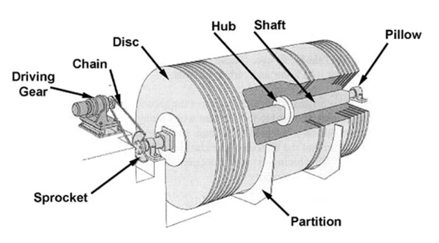
Rotating Biological Contactors
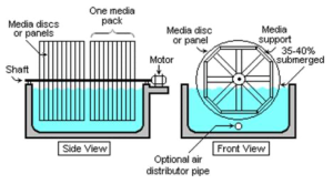
An aeration device for reducing the BOD value of a liquid effluent.
-
- Rotating Contactor 1
-

- Rotating Contactor 2
Trickling Filters
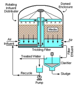
Consists of a permeable bed of rock, slag, or plastic . Wastewater is distributed over and trickles through the bed.
Wastewater Treatment Systems

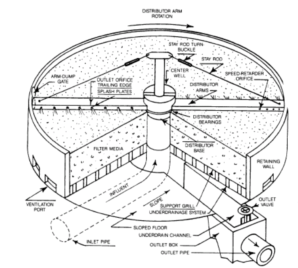
Image: Zones of Wastewater Treatment Systems
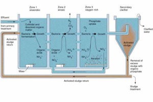
Zone 1 – Anaerobic
|
Zone 2 – Anoxic
|
Zone 3 – Aerobic
|
Wastewater is sampled and tested before it is released. Some common tests include:
pH – must be between 6.5 and 8.5.
Oxygen Levels – indicate number of bacteria and protozoa that feed on organic waste and the oxidizing chemicals affect the oxygen levels in water.
Biochemical oxygen demand (BOD)– Amount of oxygen consumed by micro-organisms.
Chemical oxygen demand (COD)- Amount of oxygen consumed by chemical oxidants in the water.
Temperature– Affects the ability of water to retain dissolved oxygen.
Suspended solids– If the solids content of the effluent is too high, some contaminants may be present in the effluent leaving the system.
BOD and COD– Affect the oxygen content of the effluent
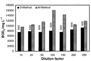
BOD Testing
Dilution Method
To ensure that all other conditions are equal, a very small amount of micro-organism seed is added to each sample being tested. This seed is typically generated by diluting activated sludge with de-ionized water. The BOD test is carried out by diluting the sample with de-ionized water with added nutrients, saturated with oxygen, inoculating it with a fixed aliquot of seed, measuring the dissolved oxygen and sealing the sample (to prevent further oxygen dissolving in). The sample is kept at 20 °C in the dark to prevent photosynthesis (and thereby the addition of oxygen) for five days, and the dissolved oxygen is measured again. The difference between the final DO and initial DO is the BOD The apparent BOD for the control is subtracted from the control result to provide the corrected value.
Manometric method
This method is limited to the measurement of the oxygen consumption due only to carbonaceous oxidation. Ammonia oxidation is inhibited.
The sample is kept in a sealed container fitted with a pressure sensor. A substance absorbing carbon dioxide (typically LiOH) is added in the container above the sample level. The sample is stored in conditions identical to the dilution method. Oxygen is consumed and, as ammonia oxidation is inhibited, carbon dioxide is released. The total amount of gas, thus the pressure, decreases because carbon dioxide is absorbed. From the drop of pressure, the electronics computes and displays the consumed quantity of oxygen.
The main advantages of this method compared to the dilution method are:
-
- its simplicity: no dilution of sample required, no seeding, no blank sample
- direct reading of BOD value
- continuous display of BOD value at the current incubation time
COD Testing
Potassium dichromate is a strong oxidizing agent under acidic conditions. (Acidity is usually achieved by the addition of sulfuric acid.).
In the process of oxidizing the organic substances found in the water sample, potassium dichromate is reduced (since in all redox reactions, one reagent is oxidized and the other is reduced), forming Cr3+. The amount of Cr3+ is determined after oxidization is complete, and is used as an indirect measure of the organic contents of the water sample.