Instrument Devices – Pressure Measurement and Control
Transducers
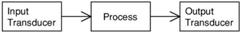
A transducer is defined as a device capable of converting energy from one form into another. It can be found at the input stage as well as at the output stage of a measuring system.
Input transducer
The input transducer, also known as a sensor, detects the desired physical quantities and converts them into another form of energy, such as electrical or pneumatic. These sensors play a crucial role in collecting data for measurement, control, and processing in various applications.
Examples of input transducers:
- Light Dependent Resistor (LDR): converts brightness of the light to resistance.
- Thermistor: converts temperature to resistance.
- Variable Resistor: converts position (angle) to resistance.
Output transducer
The output transducer, also known as the actuator, converts energy into a form that can be recognized and reacted to by another independent system. It serves the purpose of facilitating the process control loop.
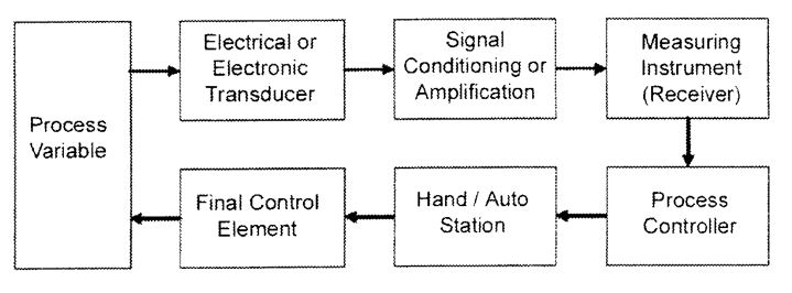
Electrical signals are used in the majority of systems to obtain:
- Economically better
- Reliable
- Accurate
- Versatile
- Require field devices that send very low voltage and low amperage electrical signals (3 – 15 mA) to the centralized control circuitry
In most cases, input transducers exhibit variations in their resistance. These resistance variations are typically converted into electrical signals, specifically voltage signals. The voltage signal is then directed to other sections of the circuit, such as the input of a transistor switch. This enables further processing and utilization of the obtained signals within the circuitry. Variable resistance can be converted to variable voltage, performed by a simple circuit called a voltage divider.
Electro-mechanical transducers
Electro-mechanical transducers are utilized for fluid pressure measurement and rely on mechanical pressure sensing elements, which include Bellows, diaphragms, and Bourdon tubes.
Transducers are categorized based on their electrical connections and principles of operation. The various classifications include:
- Voltage divider transducers
- Variable resistance transducers
- Variable inductance transducers
- Linear-Variable Differential Transformer (LVDT) transducers
- Variable reluctance transducers, also known as magnetic pickup transducers
- Variable capacitance transducers
- Strain gauges
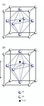
- Piezoelectric transducers
Video: What is a Vibration Sensor
Watch “What is a Vibration Sensor?” [8:16].
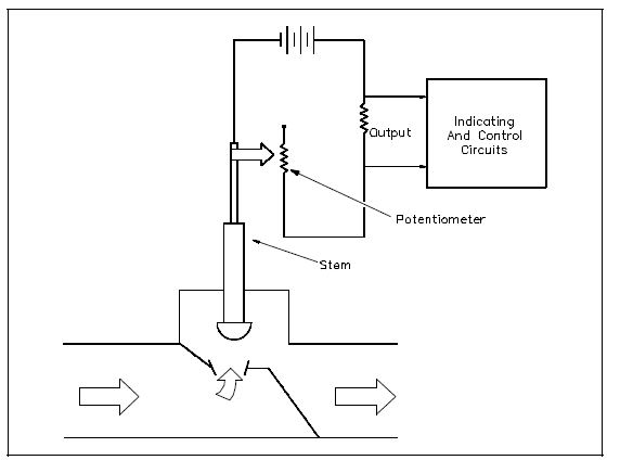
Voltage Divider Transducers
Voltage divider transducers use a Bellows or diaphragm mechanism to reposition a moving contact arm on a potentiometer. This movement causes a change in the resistance ratio and subsequently results in the measurement of the input signal.
Video: Voltage Divider Tutorial
Watch “Voltage Divider Tutorial” [3:52].
[latex]V_o = \frac{{R2 \times V_s}}{{R1 + R2}}[/latex]
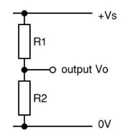
- The resistance values of R1 and R2 determine the potential outcomes in a circuit setup where they are connected in series across a supply voltage (Vs).
- This voltage is distributed between the two resistances, resulting in an output voltage (Vo) across R2.
- The behavior of Vo depends on the relative sizes of R1 and R2.
- When R2 is significantly smaller than R1, Vo is diminished due to the majority of the voltage drop occurring across R1.
- In the case where R2 is approximately equal to R1, Vo amounts to roughly half of Vs.
- Conversely, if R2 is considerably larger than R1, Vo becomes elevated since most of the voltage drop now happens across R2.
Variable Resistance Transducers
Variable resistance transducers utilize a pressure-sensing element to change the transducer’s electrical resistance.
Activity: Variable Resistance Transducer Diagram
Click on the image hotspots to explore the functions of each part of a bellows variable resistance transducer.
Click on the image hotspots to explore the functions of each part of a diaphragm variable resistance transducer.
Variable Inductance Transducers
Variable inductance transducers use the pressure-sensing element to reposition a magnetic armature, and this alters the inductance of the surrounding coil.
Activity: Variable Inductance Transducer
Click on the image hotspots to explore the functions of each part of a variable inductance transducer.
Advantages:
- They do not possess any moving electrical contacts that could wear out over time.
- There is no occurrence of signal distortion caused by friction between contact points.
Linear Variable Differential Transformer
The linear variable differential transformer (LVDT), operates by utilizing the extension shaft or control rod as a movable core within a transformer setup. The movable core moves along the primary and secondary windings of the transformer, resulting in variations in the inductance between the two windings. These variations, in turn, generate an output voltage that is directly proportional to the position of the valve or control rod extension being measured.
Activity: Linear Variable Differential Transformer
Click on the image hotspots to explore the functions of each part of a linear variable differential transformer.
Explore the activity below to learn more about linear variable differential transformers.
Coil Assembly
The coil assembly refers to the fixed component of the position sensor.
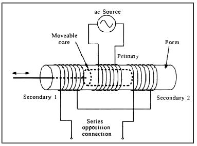
When an alternating current is applied to the primary coil, it generates opposing voltages in the secondary coils. The combined output of these secondary coils is zero when the movable core is positioned centrally, achieving a balanced or null state.
Activity: Coil Assembly
Click on the image hotspots to learn more about coil assembly.
The polarity of the LVDT’s output signal is determined by the direction of movement away from the balanced position. By externally measuring the polarity and voltage, one can accurately indicate the extent of core displacement and the corresponding fluid pressure.
Activity: Linear Variable Differential Transformer Function
Click the arrow to view how the input voltage is constant, and the output voltage can be changed based on the position of the transducer.
The LVDT consists of two secondary coils that are wound in series but in opposite directions, leading to a series-opposed configuration. This arrangement causes the two signals generated on each secondary coil to be out of phase by 180 degrees. As a result, the phase of the output signal serves as a determinant for the direction, amplitude, and distance of the measured quantity.
To learn more about the operation of RDP LVDT, you can click on this link to visit the webpage provided by RDP Group.
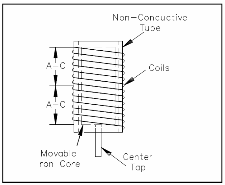
Tubular Differential Transformer
Activity: Tubular Differential Transformer
Click on the image hotspots to explore the functions of a tubular differential transformer.
Click on the image hotspots to explore the functions of a differential transformer.
The linear variable differential transformer holds an advantage over other pressure transducers due to its ability to generate an output signal that exhibits a perfectly linear relationship with the measured variable. This characteristic reduces the requirement for signal conditioning before utilizing the signal to activate an indicating device.
Variable Reluctance Transducer
The VRT is a transducer that utilizes the principle of transformer action to induce voltage into the device through motion.
Activity: Variable Reluctance Transducer
Click on the image hotspots to explore the functions of a variable reluctance transducer.
Variable Capacitance Transducer
Activity: Variable Capacitance Transducer
Click on the image hotspots to explore the functions of a variable capacitance transducer.
Advantages:
- Minimal parts are involved in their construction.
- Cost-effective option.
- High sensitivity to changes in the measured variable.
Disadvantages:
- Instruments receiving their signal are often more expensive compared to other transducers due to the complexity of the required measurement bridge circuit.
- Unsuitable for applications involving very long lead wires, as the signal tends to become unreliable.
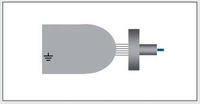
Capacitive Position Sensor
Capacitive sensors are employed for position measurement. The moving part of the sensor is depicted in a darker shade of grey, while the lines represent the distance between the two components.
The roughness of the target surface downgrades the resolution and linearity.
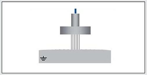
The curved surfaces lead to an averaged distance measurement.
Strain Gauges
In fluid pressure transducers, strain gauges are used to quantify the deflection experienced by a pressure-sensing element.
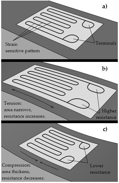
In a strain gauge, the resistance of the wire changes with elongation and compression. This change occurs because the resistance is directly proportional to the length of the conductor and inversely proportional to its cross-sectional area when the temperature remains constant.
The relationship can be expressed as:
[latex]R = kL / A[/latex]
Where:
- R = electrical resistance
- k = constant
- L = length of the conductor
- A = cross-sectional area of the conductor
Strain gauges applications include variables that impose a force such as:
- Mass
- Mechanical force
- Displacement
- Fluid pressure
To learn more about the strain gauges, click this link to visit the webpage provided by RDP Group.
Strain gauges are integrated into a measuring circuit that incorporates a temperature correction factor. When current is applied to the strain gauge, it generates heat that raises the temperature of the wire, causing a slight change in the resistance of the wire.
Semiconductor strain gauges, crafted from silicon, offer exceptional accuracy and are capable of detecting even minuscule strain variations. These gauges are particularly suitable for systems operating within the range of 0 kPa to 345,000 kPa, where there is a need to sense very small changes in pressure.
Piezoelectric Transducer
Activity: Piezoelectric Transducer
Click on the image hotspots to learn more about the functions of piezoelectric transducers.
The graphic below illustrates the piezoelectric effect and its application in generating a measurable output using a piezoelectric sensor. The drawing below provides a visual representation of the material that exhibits this effect.
Advantages:
- They do not require an external power source.
- They exhibit a dynamic response to pressure changes.
- They are compact in size and constructed to withstand harsh conditions.
- They can tolerate high temperatures, reaching up to 538°C.
Disadvantages:
- They require more sophisticated signal conditioning equipment, due to the high-impedance nature of the output signal.
- They are sensitive to fluctuations in temperature.
- When used with long lead wires, they tend to generate signal noise.
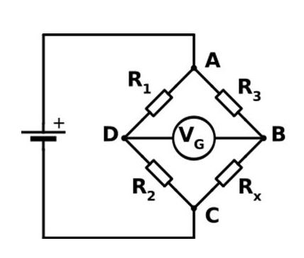
Wheatstone bridge
To determine the value of an unknown electrical resistance, a bridge circuit is employed where two legs are balanced. One of the legs incorporates the unknown component.
At the balance point, the ratio of R2 to R1 is equal to the ratio of Rx to R3.
Mathematically, Rx can be calculated using the formula: Rx = (R2/R1) x R3
Transducer Errors
Transducer errors can originate from two main sources:
- The inherent performance of the transducer itself.
- The quality and accuracy of the calibration equipment utilized for measuring its performance.
To ensure reliable and accurate results, it is essential that the test equipment employed for calibration is at least five times more precise than the device being tested. This requirement helps minimize any potential error introduced during the calibration process.
Repeatability refers to the capability of a transducer to consistently produce the same output signal when the same value is repeatedly applied.
In terms of accuracy, transducers utilizing the inductive or capacitive method tend to offer higher precision compared to devices equipped with strain gauges. The inductive method typically achieves an accuracy of around 0.001%, while the capacitive method achieves approximately 0.05%.
Resolution refers to the ability of a measurement system to detect and accurately represent small changes or increments in the measured quantity. The resolution is either clearly defined or not relevant.
Hysteresis refers to the phenomenon where there is a delay or lag between the application or removal of a force or field and its resulting effect. This effect is particularly evident in strain gauge applications. However, inductive or capacitive-based displacement transducers do not exhibit hysteresis error at all. Unlike strain gauges, these transducers do not rely on the stressing of materials to convert the input into an electrical signal.
Click here to visit Wisc-Online webpage that explains sensor hysteresis.
The three error factors together could contribute:
-
- Strain gauge – 0.26% error.
- LVDT – 0.010% error – LVDT’s don’t display any significant hysteresis effects.
Use and Placement of Pressure Transducers
Pressure transducers are designed as compact and self-contained units, offering convenience in terms of installation, calibration, and maintenance. They are commonly positioned at the end of a short nipple or tubing, which is connected to the piping containing the fluid that requires measurement.
Activity: Pressure and Dp Monitoring Locations
Click on the image hotspots to learn more about pressure and Dp monitoring locations.
In a large steam generator, fluid pressures are monitored at various points throughout the boiler, including:
- Main steam header
- ID (Induced Draft) fan gas inlet and outlet
- Precipitator or baghouse gas inlet
- Stack gas
This monitoring helps ensure proper functioning and control of the steam generator system.