Instrument Devices – Flow Measurement and Control
Flow Measurement
Most power plant flow meters are of the head type: they operate on the principle of placing a restriction in the line to cause a differential pressure head. The differential pressure which is caused by the head is measured and converted to a flow measurement. It incorporates a pneumatic or electrical transmitting system for remote readout of flow rate. The indicating instrument extracts the square root of the differential pressure and displays the flow rate on a linear indicator.
Total head H refers to the difference in head, or pressure, between two points.
H = h + P/w + v2/2g
[latex]v = \frac{{\sqrt{H - (h + \frac{P}{w})}}}{{2g}}[/latex]
Where :
- H = total head, meters
- h = height above datum level ( = 0 in this case)
- P = pressure, Pa
- w = force of gravity on 1 m3 of fluid in N
- v = fluid velocity, m/s
- g = 9.81 m/s2
Once the fluid velocity is found, the fluid flow rate is calculated.
Fluid Flow Rate
Q = Av
Where:
- Q = fluid flow
- A = cross-sectional area
- v = velocity of flow
The head flow meter actually measures the volume flow rate rather than the mass flow rate. The mass flow rate is calculated from the volumetric flow rate by knowing the temperature and/or pressure. Temperature and pressure affect the density of the fluid and, therefore, the mass of fluid flowing past a certain point.
If the volumetric flow rate signal is compensated for changes in temperature and/or pressure, a true mass flow rate signal can be obtained.
[latex]m_f = KA\sqrt{\Delta P(P)}[/latex]
[latex]m_f = KA\sqrt{\Delta P\left(\frac{1}{T}\right)}[/latex]
Where:
- mf = mass flow rate (kg-m/sec)
- K = flow coefficient
- A = area (m2)
- ∆P = differential pressure (kPa2)
- P = pressure (kPa)
- T = temperature (°C)
Flowmeters
It is assumed for calculations that the working fluid is non-compressible. If not a compressibility factor is used. The compressibility factor’s value is a function of:
- Gas-specific heat ratio
- Gas velocity
- The ratio of orifice diameter to pipe diameter in the flow-measuring element
- The ratio of upstream and downstream pressures
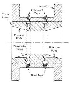
Fluid pressure impulse lines are established by tapping two specific locations within the piping or ducting system. These taps are strategically placed on opposite sides of a pipe. By doing so, the flow path of the fluid is narrowed, resulting in the generation of differential pressure.
Venturi principle
The Venturi principle explains the behavior of fluids in a system. When fluids flow through a converging stream, their velocity increases while their pressure decreases. Conversely, when the stream diverges, the opposite occurs. To minimize pressure loss due to friction, taps are positioned as close together as feasible. These taps are then connected to an instrument that measures the pressure difference between them. This measurement is utilized to determine the rate of fluid flow. Additional correction factors are needed if there is a significant amount of moisture in the gas, or if the gas is used under cryogenic conditions.
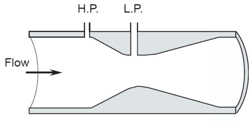
Venturi tubes
Venturi tubes are highly precise devices for sensing flow, provided they are appropriately calibrated. These tubes consist of three main components: a conical inlet that converges, a cylindrical throat, and a recovery cone that diverges. Importantly, venturi tubes do not have any structures protruding into the fluid, nor do they possess sharp corners or sudden alterations in contour.
Activity: Venturi Tube
Click the image hotspots to learn more about Venturi tubes.
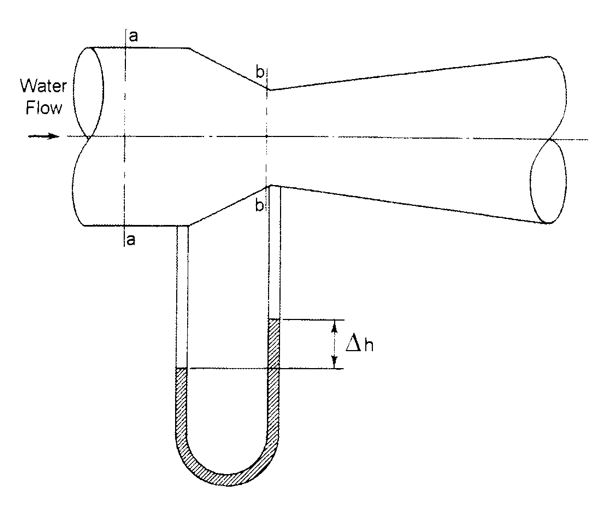
The calculation of flow is based on the Equation of Continuity.
Q = Aa va = Abvb
Activity: Venturi Tube Calculation
Click the image hotspots to learn more about Venturi tube calculations.
Calculation of flow
va = (Ab/Aa)vb = (db/da)2 vb
Where:
- da = internal piping diameter at a-a
- db = throat diameter at b-b
Activity: Venturi Tube Calculation
Click the flash card to view an example of a venturi tube calculation and the solution.
Friction is accounted for in flow calculations by multiplying the calculated flow by a coefficient of discharge. The coefficient of discharge varies depending on the design of specific Venturi tubes.
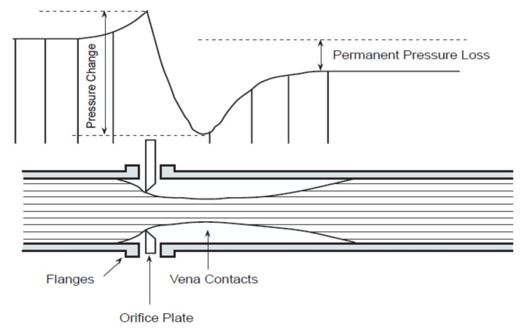
Orifice Plates
- The simplest flow path restrictions are used in flow detection.
- They are the most economical option.
- These plates are flat and have a thickness ranging from 1/16 to 1/4 inch.
- Typically, orifice plates are mounted between a pair of flanges.
- They are installed in a straight run of smooth pipe to minimize disturbances to flow patterns caused by fittings and valves.
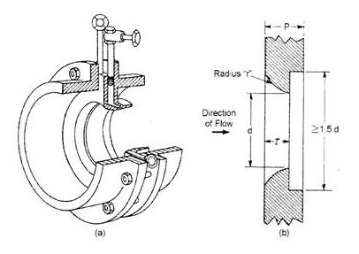
Orifices
Orifices are designed with a bevel, where their downstream diameter is slightly larger than their upstream diameter. This bevel creates a diverging effect for the fluid stream and also helps to reduce wear on the orifice.
Activity: Orifice Plate
Click the arrow to view orifice plates.
Generally, taps are placed in three different combinations of locations:
- As part of the orifice flanges.
- One pipe diameter upstream and two diameters downstream of the orifice, resulting in the maximum pressure drop.
- 2.5 pipe diameters upstream and eight diameters downstream of the orifice, creating a pressure drop equivalent to the total pressure loss in the piping.
Activity: Orifices Plates
Click the arrows to see the different orifice plate placements.
Advantages:
- Least expensive measuring element to purchase for flow measurement.
- Easily installed in an existing pipe run.
Disadvantages:
- Cause a high permanent pressure drop: 60% to 80% of inlet pressure.
- Subject to erosion which will cause inaccuracies in the measured differential pressure.
- Cannot be used on dirty fluids, slurries, or wet steam as erosion will alter the differential pressure generated by the orifice plate.
Orifice Plate Designs
Dall short insert tube: uses two pieces that produce a venturi-like internal shape. It also produces a very low-pressure drop relative to other designs, but it is susceptible to clogging if there is particulate matter contained within the working fluid.
Quarter-circle orifice plate: has a rounded leading edge and oversized trailing edge and is particularly useful when the working fluid is very viscous.
Flow Nozzles
Flow nozzles represent a design compromise between a Venturi tube and an orifice plate. They provide an intermediate option in terms of cost. Flow nozzles are commonly employed in large flow applications due to their compact design.
Activity: Flow Nozzle Installation
Click the image hotspots to learn more about flow nozzle installation.
Gentile Flow Tube
The orientation of taps serves to minimize the resulting pressure drop and turbulence.
Video: The Differential Pressure Flow Measuring Principle
Watch “The Differential Pressure Flow Measuring Principle (Pitot tube)” [4:36].
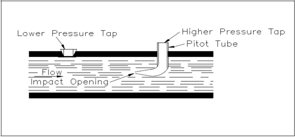
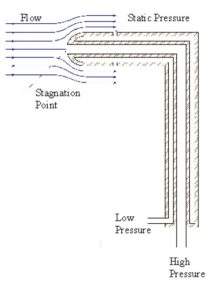
Pitot Tubes
Pitot tubes consist of a tube with a small hole at the end. They are positioned in a way that the tube faces the flowing fluid. As the fluid enters the opening of the tube, its velocity gradually decreases to zero. Pitot tubes are primarily used to measure high-pressure inputs for differential pressure detectors. A pressure tap is employed to capture the low-pressure input.
Activitie: Pitot Tubes
Click the image hotspots to learn more about pitot tubes.
Click the image hotspots to learn more about pitot tube arrangement with two concentric tubes.[
h5p id=”65″]
Pitot tubes find frequent application in gas flow measurement, including their usage in airplanes to determine airspeed.
Advantages:
- Simplicity and cost-effectiveness in design.
- Only require one small opening to be made in piping or ductwork.
- Resulting in negligible pressure drop or loss.
Disadvantages:
- Pitot tubes measure velocity from a single point in the fluid stream.
- Certain fluids exhibit varying velocities at different locations within their cross-section.
- To obtain a series of readings, the pitot tube needs to be moved across the fluid flow path.
- Multiple sets of pitot tubes at different locations in the pipe or duct cross-section are required to capture velocity variations.