Part 4
Control Systems
Types of systems in modern use:
- Distributed Control Systems (DCS)
- Supervisory Control And Data Acquisition (SCADA) systems,
- Building Management Systems (BMS)
Distributed Control Systems (DCS)
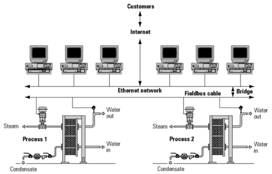
Distributed control systems are control systems where the controller elements are not central in location but are distributed throughout the system. Each component sub-system is controlled by one or more controllers. The entire system of controllers is connected by networks for communication and monitoring.
Activity: Distributed Control Systems
Click the arrows to see diagrams of distributed control systems.
DCS Objectives:
- Safe operation of the plant
- Lowest cost of generation
- Longest equipment life
- Minimum environmental effect
- Maximum efficiency
- Energy conservation
DCS Benefits:
- High reliability
- Improved response time
- Improve operator interface to plant
- Improve accessibility of plant data to engineering & management personnel
- Historical storage and retrieval system
The distributed control system is process-oriented as it considers the power plant as the center of the universe and presents data to operators as part of its job in managing the controlled process. The DCS is always connected to its data source, therefore it doesn’t need to maintain a database of current values. Redundancy is usually handled by parallel equipment, not by diffusion of information around a distributed database
The DCS uses microprocessors to manage control functions from a series of computer monitors. This enables various functions to be managed from an integrated display, showing clearly the interaction and interdependence of various control loops. The operating staff benefits from a larger quantity of readily available useful information, presented in a user-friendly and configurable format tailored to their specific needs.
Activity: Distributed Control Systems Components
Click the image hotspots to see the components of a distributed control system.
DCS Operator Station
The DCS operator station is directly connected with its I/O through local wiring, FieldBus, networks, etc. When the DCS operator wants to see information he usually makes a request directly to the field I/O and gets a response. Field events can directly interrupt the system and advise the operator.
A plant DCS has the following characteristics:
- The operator interface can be either through individual digital control stations for each controlled variable or through a monitor screen with a keyboard and mouse or other input device.
- Considerable flexibility is available for configuring the control loops because the control functions are largely embedded in the computer software rather than in the hardware. Plant operators are often involved in the initial design of the interface in order to ensure that it meets their needs.
Maintenance
- Control loop tuning, diagnostics, and configuration can be done using the system software. Control tuning can be done while viewing the results of their adjustments in real-time from a single CRT.
- Modular hardware makes the replacement of faulty equipment a quick and simple process and reduces the amount of parts inventory that must be maintained.
Device Communication
Fieldbus is a generic term used to describe a digital communications network that is used to replace the existing 4 – 20mA analog signal. The network is a digital, bi-directional, multidrop, serial-bus, communications network that is used to link isolated field devices, such as controllers, transducers, actuators, and sensors. Each field device has low-cost computing power installed in it, making each device a ‘smart’ device. Each device is able to execute simple functions on its own. For example diagnostic, control, maintenance, and bi-directional communication functions.
Distribution Control System Advantages:
- Reduction in system hardware: fewer controllers and less wiring required to control processes.
- Reduction in installation costs: less equipment to install, the installation is simpler and quicker. Reduction in material and labor costs for installing wire, cable tray, conduit, marshaling cabinets, junction boxes, and terminal blocks.
- Less space required: less equipment and less wiring in the control room mean more space is available for other uses.
- Engineering drawings: the computer automatically produces accurate and up-to-date process logic drawings.
- Safety: fault state actions are embedded in the software with specific actions defined. In the event of a failure of the main computer, control falls back to the ‘local’ bridges which have independent power supplies and are programmed to default to a ‘safe mode’ relevant to the process.
- Increased process information: the amount of information available to operators and management is increased many times.
- Proactive maintenance: the main computer can carry out detailed diagnostic routines, testing for sensor failure, output failure, memory failure, configuration error, communication error, valve position and valve travel time used, stick-slip action, and so on. Maintenance and calibration are based on the actual condition of the device rather than a time period.
- System reliability: proactive maintenance means that equipment is well maintained.
- Quality control: centralized control and the ability to view the process in parts or in total, improves quality control.
- Stock holding: improved response and flexibility from the plant means that the product inventory can often be reduced.
- Spares: because of the compatibility and interchangeability of components, the user is not tied to one component supplier.
- Communications: control system or any of its components may be accessed from virtually anywhere, either over computer networks, or the Internet.