Part 5
The HART Protocol
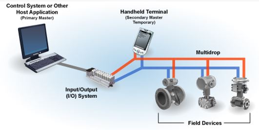
Highway Addressable Remote Transducer (HART) Protocol is an early implementation of Fieldbus, a digital industrial automation protocol. The global standard for sending and receiving digital information across analog wires between smart devices and control or monitoring systems. These devices can communicate over legacy 4-20 mA analog instrumentation wiring.
There are two main operational modes of HART instruments:
- Peer to Peer (Analog/Digital) mode: digital signals are overlaid on the analog 4-20 mA loop current. Both the 4-20 mA current and the digital signal are valid output values from the instrument. Only one instrument can be put on each instrument cable signal pair.
Activity: Analog/Digital Mode
Click the arrows to learn more about analog/digital mode.
- Multidrop (digital) mode: only the digital signals are used, an analog loop current is fixed at 4 mA. It’s possible to have up to 15 instruments on one signal cable however each instrument needs to have a unique address.
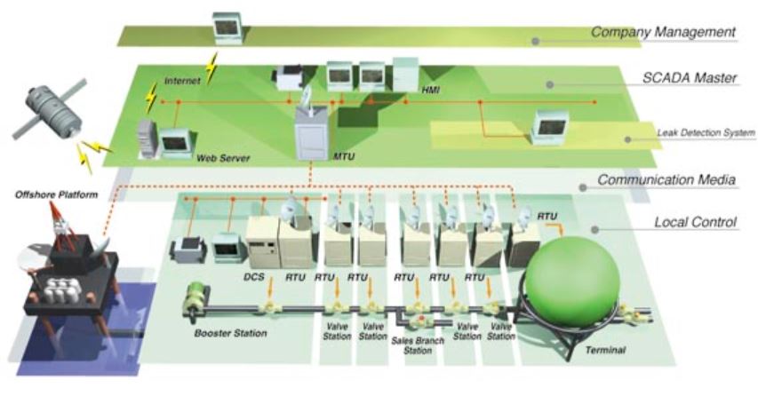
Supervisory Control and Data Acquisition (SCADA)
SCADA consists of three main elements:
- Remote Telemetry Units (RTU): collects information at a site, brings that information from the various plant RTU sites to a central location, and returns instructions to the RTU.
- Human Machine Interface (HMI): displays information in an easily understood graphics form, archives the data received, transmits alarms, and permits operator control as required. It’s essentially a PC running powerful graphic and alarm software programs.
- Communications: within a plant will be by data cable, wire, or fiber-optic, while regional systems most commonly utilize radio.
Activity: SCADA
Click the image hotspots to learn more about SCADA systems.
Data Acquisition System (DAS)
Data acquisition systems typically involve the conversion of analog waveforms into digital values for processing.
The components of data acquisition systems include:
- Sensors that convert physical parameters to electrical signals.
- Signal conditioning circuitry to convert sensor signals into a form that can be converted to digital values.
- Analog-to-digital converters, which convert conditioned sensor signals to digital values.
Data logging systems consist of four elements:
- Measuring output (sensors around the vehicle)
- Recording output signals (logger unit)
- Uploading/accessing recorded data (telemetry)
- Analysis of recorded data. (DAQ software)
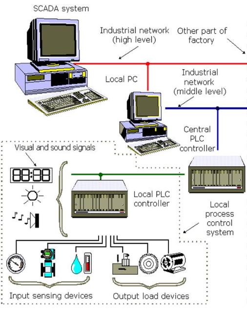
Distributed Control Systems
Other data transfer methods that are commonly used:
Ethernet:
- TCP/IP (Transmission Control Protocol/Internet Protocol): internet or wireless Ethernet enables plant operation from a remote location.
- UDP (User Datagram Protocol).
Disadvantages:
- Hardware, and sometimes the software, can be be proprietary in nature, and components from different vendors do not always work together.
- The cost of a DCS installation can be quite high in comparison to the use of conventional panel-mounted or local controls.
- Specialized training is needed for the operators using the system and for the people maintaining it.
- Substantial increase in the number of alarms that operators must deal with. Nuisance alarms, or alarm information that is unclear, can be a serious distraction during times of plant upsets.
Operator Interfaces
Human Machine Interface (HMI)
HMIs are used for:
- Data Acquisition System (DAS): display of data.
- Supervisory Control and Data Acquisition (SCADA): direct control of plant equipment.
CRT Consoles
CRT consoles are extensively used to display process information in a series of hierarchical levels.
- Level 1: information for a single control loop is displayed.
- Level 2: displays information for a group of related loops.
- Level 3: displays an area of the plant, one complete process, or perhaps the area for which a single operator is responsible.
Activity: Operator Display
Click the arrows to view examples of operator displays.
Smart Devices
Smart field devices are field sensors and transmitters that contain their own microprocessor diagnostic circuitry.
They can provide the following information:
- Information about the device itself: tag number and name, name or number of the process variable it is associated with, manufacturer and model number, installed software revision number, and serial number.
- The status of the device, including coded detail about any malfunctions or irregularities.
- Records of any configuration changes that have been made.
- Calibration data, such as the engineering units used the upper and lower range and limit values, span, signal damping, and date, time, and results of the last calibration.
Smart devices can be contacted electronically to run:
- Self-diagnostic check: self calibrations are also sometimes possible.
- Other Capabilities: online configuration from central local and can enable an operator to poll a transmitter in order to ensure that it is functioning normally.
Programmable Logic Controller (PLC)
A PCL is a digital computer used for the automation of industrial processes. Designed for multiple inputs and output arrangements, extended temperature ranges, immunity to electrical noise, and resistance to vibration and impact. Programs to control machine operation are typically stored in battery-backed or non-volatile memory.
Examples of PLCs:
- Sootblowers
- Fuel handling
- Ash handling
- Compressed air
- Water treatment
- Plant site security
PLCs can be constructed in a modular fashion. Plug-in modules either receive data from a certain number of inputs (usually up to 32) or transmit switching instructions to a certain number of outputs (usually up to 16). The modules are plugged into an input/output rack (I/O rack). The CPU manages both the input and output functions through two-way communication with them.
The input signals can be either AC or DC and can be at voltages ranging from a few volts to 230 V. The input modules receive information from field devices and convert it into digital data before sending it to the CPU. The output signals are at similar voltage levels to the input signals.
A PLC is not intended to manage a modulating control loop, only to switch output devices from one position to another. The flexible control that a PLC offers can be enhanced by including timers and counters so that a given output will only occur after a preset delay time, or only after a given input or routine has occurred a preset number of times. The CPU includes a series of registers, which are memory locations where the on or off status of each input and output is retained. The status of the registers in order to monitor any change in the switch position of any inputs or outputs.
The CPU memory circuits that retain the user program may be:
- Volatile memory, which requires a continuous power supply. A battery backup is required for the power supply as a power failure would require manually re-inputting the user program.
- Electrically Erasable Programmable Read-Only Memory (EEPROM), which does not require a power source.
Advantages:
- Switching output devices according to the changing demands of the input signals can be done automatically, without human intervention.
- The internal static switches used for outputs eliminate the wear and required maintenance of more conventional magnetic relays that would otherwise control the switching circuits.
- Additional functions, or an expanded system, can often be added by plugging additional I/O modules, or even an additional CPU, into the PLC rack. If needed, additional racks can be connected to create a larger, more powerful system.
- Changes to the user program are relatively easy to accomplish.
- Compared to a conventional process control system, the number of wires needed for connections is reduced by 80%
- Consumption is greatly reduced because a PLC consumes less energy than a bunch of relays
- Diagnostic functions of a PLC controller allow for fast and easy error detection.
- Change in operating sequence or application of a PLC controller to a different operating process can easily be accomplished by replacing a program through a console or using PC software.
- Needs fewer spare parts
- It is much cheaper compared to a conventional system, especially in cases where a large number of I/O instruments are needed and when operational functions are complex.