Instrument Devices – Flow Measurement
Use and Placement of Flow Measuring Devices
The usage and placement of flow-measuring devices require a minimum length of straight piping both upstream and downstream of the measurement point. This guarantees that the fluid flow experiences minimal turbulence before being measured. It is crucial to avoid placing the metering element near any bends or curves in the piping to ensure accurate measurements.
Fluid Flow Measurements
The output signals are directed electrically to the indication instruments and process control devices. May be a considerable distance away in a centralized control room or remote building.
Gas Flow Measurement
Somes flow can be measured from differential pressure without having to have a differential pressure sensing element installed.
For example gas flow measurement across an economizer or air preheater, where the equipment itself produces a pressure drop that can be utilized to calculate flow rates.
Flow Meter Installation
Taps for pressure sensing for a flowmeter. Do not install it at the bottom of a pipe. Scale, condensation, or other contaminants must not obstruct the taps.
Taps are located:
- On top of the pipe for gas applications
- On the side of the pipe for liquid or steam
Flowmeter
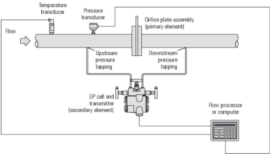
Flowmeters are comprised of two parts:
- Primary Element
i.e., orifice plate, located in the steam flow. - Secondary Element
i.e., differential pressure cell that translates any signals into a usable form.
Additional Requirements
An electronic processor that can receive, process, and display the information. May also receive additional signals for pressure and/or temperature to enable density compensation calculations to be made.
Activity: Head Flow Measurement
Click the image hotspots to learn about head flow measurement.
Examples:
-
- Orifice flow meter: the primary flow element in an orifice flow meter is the differential pressure across the orifice plate.
- Turbine meter: equipped with a magnetic pickup that senses the proximity of the turbine blades. The rotation of the turbine caused by fluid motion is detected by the magnetic pickup, serving as the primary flow element for a turbine meter.
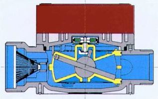
- Diaphragm/Bellows meters and other positive displacement meters: equipped with a crankshaft that rotates as fluid flows through the meter.The rotation of the crankshaft acts as the primary flow element in these types of flowmeters.
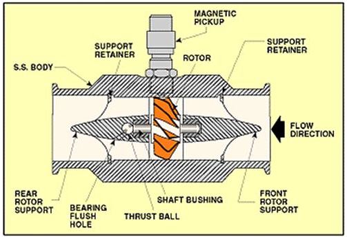
The turbine flowmeter consists of a multiple-bladed, free-spinning, permeable metal rotor housed in a non-magnetic stainless steel body. In operation, the rotating blades generate a frequency signal proportional to the liquid flow rate, which is sensed by the magnetic pickup and transferred to a read-out indicator.
Types of Flow Meters:
- Orifice
- Venturi Tube
- Flow Nozzle
- Pitot Tube
Activity: Flow Meters
Click the arrows to see images of the different types of flow meters.
Primary Element Advantages and Disadvanges
|
Primary Elements |
|
| Advantages |
Disadvantages |
|
Orifice |
|
|
|
|
Flow Nozzle |
|
|
|
|
Venturi tube |
|
|
|
Manometers
A manometer is a pressure-measuring instrument, usually limited to measuring pressures near to atmospheric.
Manometers types:
- Simple Manometer
- Micromanometer: for precision readings. (Vertical tube manometer and inclined tube manometer)
- Differential manometer: for pressure differential across two sources.
- Inverted differential manometer: used for measuring the difference of low pressures, where accuracy is the prime consideration.
Activity: Manometers
Click the arrows to see diagrams of the different types of manometers.
Ring Balance Manometer
Ring balance manometers have two measuring legs that are two sections of a hollow circular ring separated by an internal partition. The two pressure connections are flexible and are joined to the ring on either side of the partition. The ring itself is free to rotate around a central pivot point. Differential pressure causes the contained liquid to move from one side of the ring to the other creating a rotating moment which causes the ring to rotate away from the higher pressure. A counterweight is used to create an opposing moment, and when the two moments are in balance, the motion stops. The degree of rotation of the ring before equilibrium is reached indicates the magnitude of the differential pressure, and a pointer attached to the ring indicates movement on a scale that can be calibrated to indicate units of differential pressure or of fluid flow.
On a common type ring balance flowmeter, the counterweight is attached to a shaped cam, imparting a rotating moment to the cam. The cam’s angular motion provides the output signal or indication. The cam is shaped to give square root compensation needed for direct flow measurement.
Forced Balance
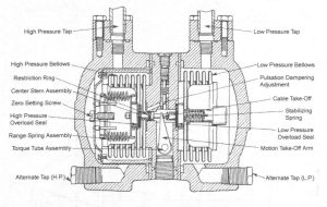
Utilizes the feedback of the output signal to balance the primary input signal from the measuring element. The balanced output signal is proportional to the measured variable. In this device, two bellows are used back to back and either the high-pressure or low-pressure connection of a differential-pressure primary measuring device supplies each one. The balanced output is conveyed through the motion take-off arm on the front of the device’s case.
Target Flow Meter
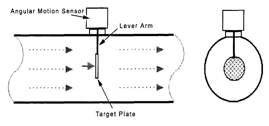
Advantages:
- Low initial set-up cost.
- Can be used in abrasive, contaminated, or corrosive fluid flow.
- Can be made to measure flow velocity that is sporadic or multidirectional with sphere drag element designs.
Disadvantages:
- Pressure drop is inevitable due to the rod and the drag element.
- Less popular than it was before.
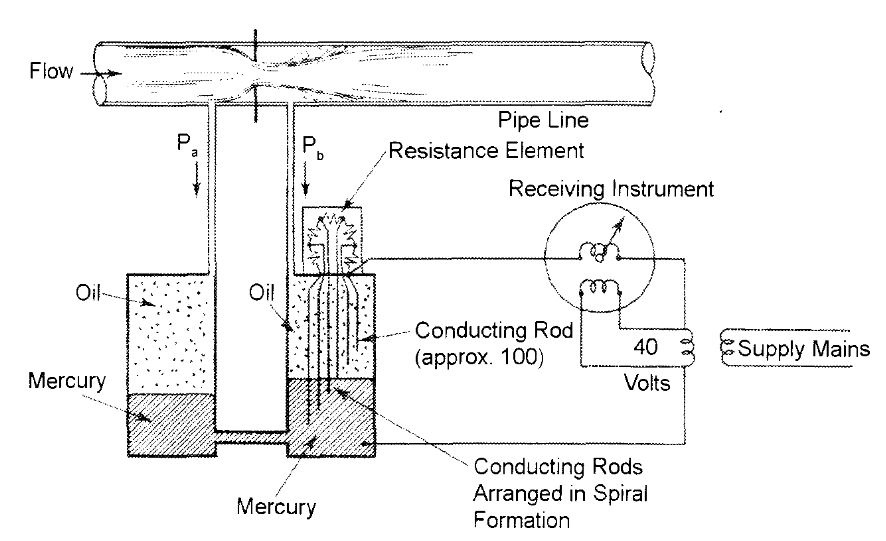
Electric Flow Indicating Mechanisms
Manometers can be used to generate electrical signals that can be used in a fluid flow control circuit.
- About 100 rods with varying lengths are used.
- The mercury level determines the amount of resistance in the circuit.
- The entire unit is filled with oil above the mercury level so that the fluid measured does not contaminate the conducting rods.
Magnetic Flow Meter
Also called Mag Flow Meter, consists of a length of electrically insulated pipe, two coils opposite each other, and a series of electrodes that are flush with the pipe’s interior insulation lining.
Activity: Magflow Meter
Click the arrows to view images of magflow meters.
Advantages:
- Well-suited to measuring flows of liquids that contain quantities of suspended particulate that would wear or clog a conventional element.
- Able to measure flows accurately even when there are significant changes in the liquid viscosity, density, temperature, pressure, and conductivity.
- Produces no appreciable pressure drop.
- Has a very wide range of measurements.
Disadvantages:
- The liquid being measured must be electrically conductive.
- Very low liquid velocities cannot be measured effectively.
- Electrodes can be contaminated by the fluid flow.
Hot-wire Anemometer
A hot-wire anemometer is a device used to gauge the flow of air or fluid. It operates by directing the flow to intersect a heated filament located on a sensor. As the flow passes over the filament, it induces a change in temperature. This alteration in temperature is directly proportional to the movement of the flow across the filament.
Activity: Hot-Wire Anemometers
Click the arrows to learn more about not-wire anemometers.
Use and Placement of Flow Measuring Devices
Flow measuring devices are strategically positioned within boiler rooms to accurately measure critical flows.
Activity: Flow Monitoring Locations
Click the host spots to learn about the flow monitoring locations on a boiler.