Part 1: Instrumentation and Control Systems
On/Off Control
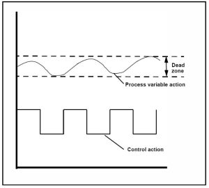
On/off controls in power plant systems refer to binary mechanisms that enable or disable the operation of specific equipment or processes to regulate power generation and manage plant components. This type of control doesn’t actually hold the variable at the setpoint but keeps the variable within proximity of the setpoint in what is known as a dead zone.
Activity: On/Off Control
Click the arrows to see images of on/off control.
To ensure accurate measurement, pressure changes need to be amplified. This amplification is achieved through the utilization of a pneumatic amplifier, also known as a relay. The pneumatic amplifier enhances the magnitude of the pressure change, allowing for more precise measurements to be taken.
Activity: Pneumatic Relay
Click the image hotspots to learn more about pneumatic relays.
When the nozzle is covered: the pressure in the associated chamber builds up, causing the conical valve to close the exhaust port and the ball valve to allow air to flow from the supply to the output port so that the output pressure rises.
When the nozzle is uncovered: the flexible diaphragm moves to that the ball valve restricts the flow of air from the supply. At the same time the conical calve moves off its seat, opening the exhaust so that the output pressure falls.
On/Off control involves a control signal that is either 0% or 100%. Achieving precise control at the setpoint may be challenging, so a deadband is incorporated. This type of control is useful for large, slow systems, particularly those with electric heaters. The deadband prevents frequent switching and helps maintain a stable temperature.
Proportional Control
Corrective Action is proportional to the amount of error. Output is modulated rather than operating in a repeating on/off cycle.
Activity: Proportional Control Amplifier
Complete the activity below to learn more about proportional control amplifiers.
Activity: Proportional Control
Click the arrows to view images of proportional controls.
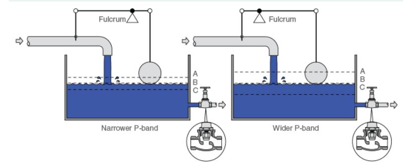
Proportional control operates by adjusting the control valve in proportion to the deviation between the actual water level and the desired set point. However, the set point can only be maintained under a specific load condition.
Although stable control can be achieved between points A and C, any load that causes a difference in the water level from point B will consistently introduce an offset. This means that the control system will not be able to maintain the exact set point when operating under different load conditions.
The image below demonstrates the relationship between P-band and offset.
Proportional Gain
The proportional gain refers to the ratio of the change in the controller’s output to the change in the measured variable. In a control system, the controller adjusts its output in proportion to the error between the setpoint (SP) and the process output (PV). This means that the magnitude of the controller’s movement is directly related to the difference between the desired setpoint and the actual process output. Mathematically, the proportional gain is determined by dividing the change in the controller’s output by the change in the input or measured variable.
Activity: Controller Offset
Click the arrows to view the difference between low gain and high gain.
A change in controller input will result in a change in controller output. This adjustment aims to eliminate the error by appropriately positioning the valve. It is important to ensure that the change in output is sufficient to address the error without causing instability or cycling.
The proportional gain calculation is:
Gain, (Kc) = ∆Output%/∆Input %
For example:
- Change in Input to Controller – 10%
- Change in Controller Output – 5%
Gain = 5%/10% = 0.5
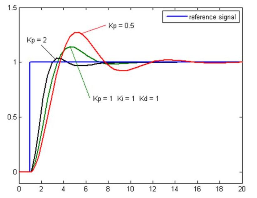
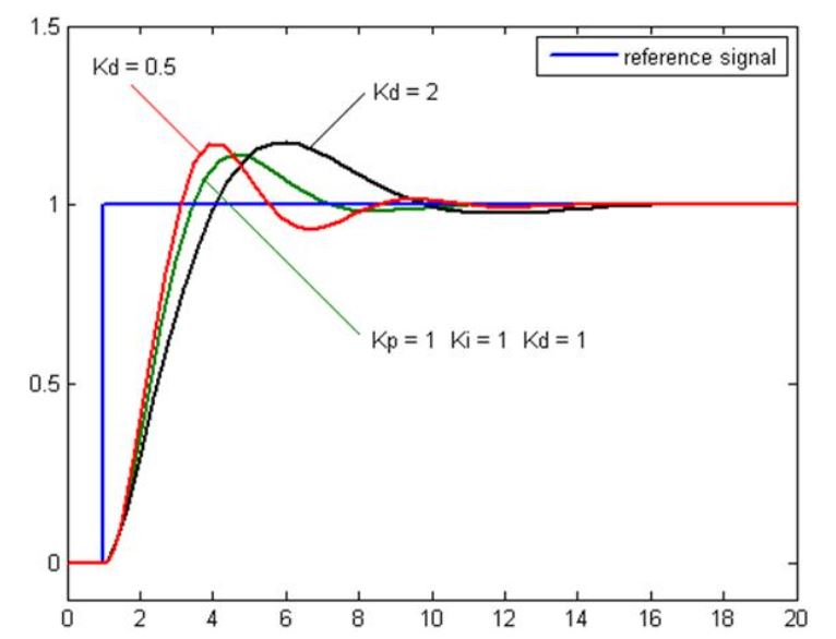
The plot of PV vs Time, for three values of Kp (Ki and Kd held constant)
- Kp = Proportional Gain
- Ki = Integral Gain
- Kd = Derivative Gain
Controller Output
Direct Acting
- Controller output decreases as the measured variable increases.
- The gain is positive.
Reverse Acting
- Controller output increases as the measured variable increases.
- The gain is negative.
Proportional Band
In a controller, the proportional band is the inverse of the gain.
PB = ∆Input (% Span) For 100%∆Output
Gain=100%/PB
PB = 100/Gain
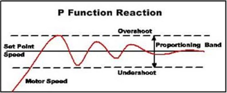
Proportional Action
Limits of proportional action:
- Proportional action responds only to a change in the size of the error.
- Proportional action will not return the Process Variable (PV) to the setpoint.
- Offset is a constant deviation of the process variable from the setpoint.
- It will, however, return the PV to a value that is within the Proportional Band (PB) around the PV.
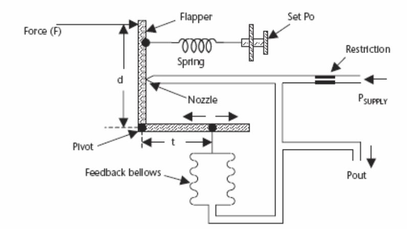
Flapper/Nozzle System
Activity: Flapper/Nozzle System
Click the image hotspots to learn more about the typical flapper/nozzle system.
A pressure gauge is connected to the “T” junction.
- The pressure is high when the nozzle is covered by the flapper.
- Pressure is lower when the flapper moves away from the nozzle.
Activity: Proportional Control System
Click the arrows to learn more about proportional control systems.
Proportional controls provide a control signal, proportional to the magnitude and direction of the error signal. A change in the control signal requires a change in the error signal, therefore offset will occur. Proportional control stabilizes an error; it does not remove it.
Integral Control
The controller output is proportional to the amount of time the error is present. Integral action eliminates the offset that remains when proportional control is used. Adding a reset to the controller adds one more gain component to the loop. The faster the reset action, the greater the gain.
Integral control settings
Integral, or reset action, may be expressed in terms of:
- Repeats Per Minute: how many times the proportional action is repeated each minute.
- Minutes Per Repeat: how many minutes are required for 1 repeat to occur?
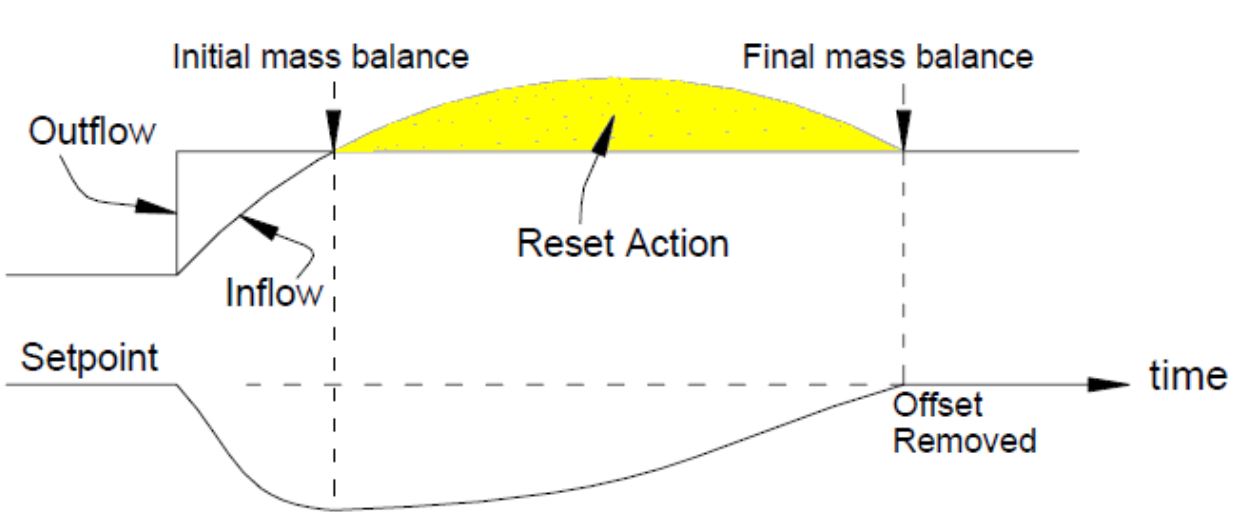
Additional Control Signal Restores Process to Setpoint
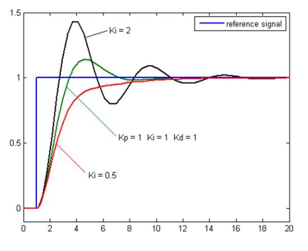
The plot of PV vs Time, for three values of Ki (Kp and Kd held constant)
- Kp = Proportional Gain
- Ki = Integral Gain
- Kd = Derivative Gain
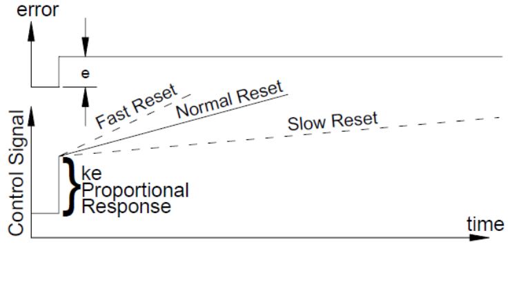
Fast Reset
- High gain: large repeats/min.
- Fast return to the setpoint.
Slow Reset
- Low gain: small repeats/min.
- Slow return to the setpoint.
- Stable loop.
Proportional Plus Integral Control (PI)
Reset
Activity: Reset
Click through the activity below to learn more about integral reset settings.
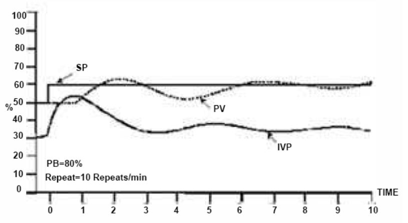
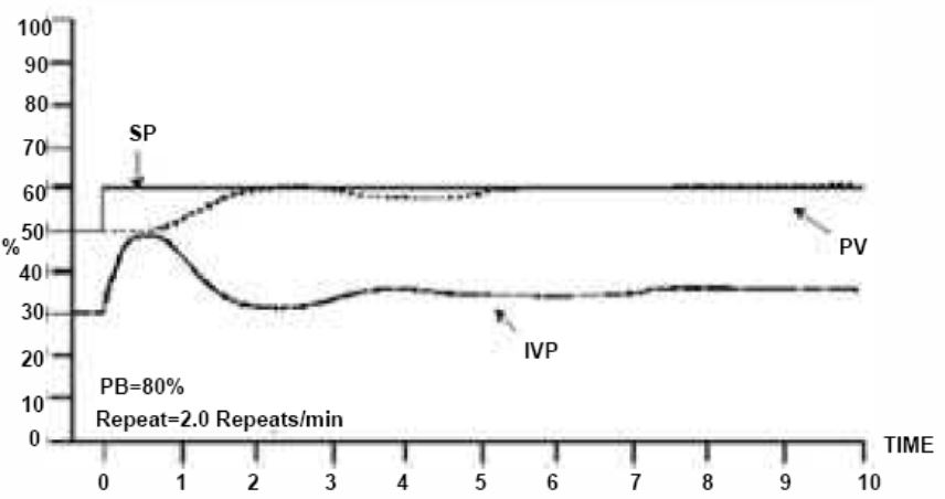
Boiler Proportional-Plus-Reset Control
Activity: Boiler Proportional-Plus-Reset Control
Click the arrows to view diagrams of Boiler Proportional-Plus-Reset Control.
Integral (Reset) Action
Integral (Reset) Action, also known as reset control, is a crucial component in control loops. Its primary purpose is to eliminate any offset in the system. The units for integral action are either Repeats per Minute or Minutes per Repeat, depending on the application.
The function of Reset Action is to reduce the stability of the control loop. It’s important to exercise caution when applying reset control to process loops, as it may lead to sustained errors. If the control signal is rapidly adjusted to the extreme value, a phenomenon called “reset windup” can occur. To avoid these potential issues, it is essential to implement integral action with care and consideration for the specific system requirements, ensuring that it effectively removes offset without compromising the stability and accuracy of the control loop.
Proportional-plus-Integral-plus-Derivative Control (PID)
Proportional-plus-Integral-plus-Derivative Control, commonly known as PID control, is a widely used control technique. One of the essential components of PID control is the Derivative (Rate) Action.
In certain scenarios, especially with large and slow processes like a large liquid level control or a heat exchanger, the response to small changes in the controller output might be inadequate. These processes may react very slowly to minor adjustments in the control signal.
To enhance the response and improve control performance, the derivative mode comes into play. The derivative action introduces a large initial change in the controller output. This significant change helps in initiating a prompt response from the process, allowing the system to overcome its inertia and react more effectively to changes in the control signal.
By using the derivative mode in the PID control strategy, engineers can achieve better control over large and slow processes, enabling a more efficient and responsive control system. However, it is essential to carefully tune the PID parameters to avoid excessive oscillations or instability in the control loop. With proper tuning, PID control can optimize the performance of diverse industrial processes.
To add derivative action to a pneumatic proportional-plus-reset controller, it is necessary only to add a restriction in the airline to the feedback bellows.
Derivative (Rate) Control
Activity: Derivative (Rate) Control
Use the slider to learn more about derivative (rate) control.
Video: Derivative Control Mode
Watch “Derivative Control Mode Analogy” [3:24].
Derivative (Rate) Action
Derivative (Rate) Action also referred to as termed rate provides some extra control signal based on the rate of change of the error signal, typically combined with proportional control. It is an anticipatory control that offers a significant initial control signal to limit the final deviation, enhancing the system’s responsiveness and reducing error.
The plot of PV vs Time, for three values of Ki (Kp and Kd held constant)
- Kp = Proportional Gain
- Ki = Integral Gain
- Kd = Derivative Gain
Activity: Proportional Plus Derivative
Scroll through the information wall to learn more about Proportional Plus Derivative.
Activity: Proportional-Plus-Reset-Plus-Rate
Click the arrows to learn more about Proportional-Plus-Reset-Plus-Rate.