Instrument Devices – Level Measurement and Control
Ball-Float Devices
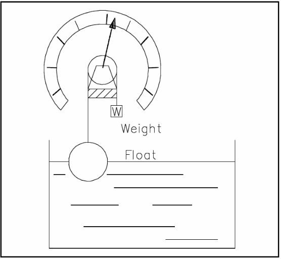
A ball-float directly measures the liquid level in a column.
Activity: Float Level Indicator
Click through the images to see the different types of float-level indicators.
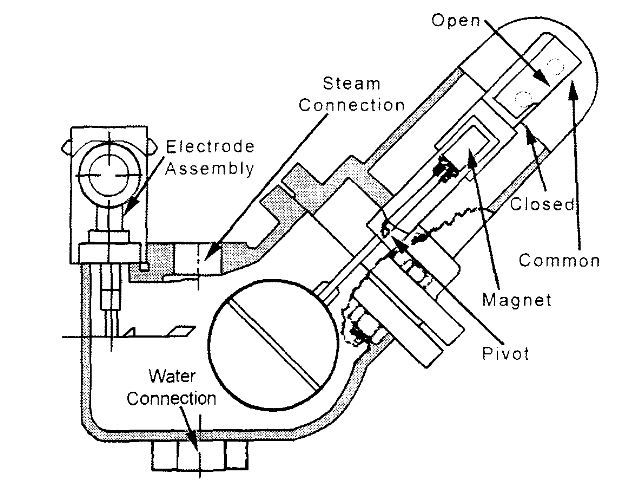
Float Cage
The float cage serves as a primary element for detecting water levels in process vessels and boiler drums. It consists of a cage that encloses a float, which allows the level to be visually observed from outside the vessel. In addition to level indication, the float cage offers various functions such as high and low-level alarms, pump start-stop control, and control valve open-close operations.
Variable-Displacement Devices
Activity: Variable-Displacement Device
Click the hotspots to learn about variable displacement devices.
Advantages:
- Measuring devices can be compact.
- Sensitive to small changes.
Disadvantages:
- Does not produce an output force that is linearly proportional to the changes in the liquid level.
Chain Float Cage
Chain float cages work by utilizing a buoyant float attached to a chain, which is connected to a mechanical or electrical measuring system. As the liquid level changes, the float moves up or down along the chain, transmitting the corresponding level information to the measurement device, enabling accurate monitoring and control of liquid levels in various applications such as power engineering.
Hydrostatic Head Device
The pressure is a function of the height, or head, of the amount of liquid in the vessel. The gauge can be safeguarded by employing a sealing and transmitting medium, such as air or oil, in the piping connecting the measured liquid and the gauge, enhancing measurement sensitivity.
Video: Measuring Liquid Level Using a Pressure Gage
Watch “Video Tutorial: Measuring Liquid Level Using a Pressure Gage” [6:53].
Activity: Hydrostatic Head Device
Click the arrows to learn about the types of hydrostatic head devices.
Bubbler
Bubblers are typically used in tanks open to the atmosphere.
Video: Measuring Liquid Level Using a Bubbler
Watch “Tutorial: Measuring liquid level using a bubbler” [7:38].
Activity: Bubblers
Click the arrows to view diagrams of bubblers.
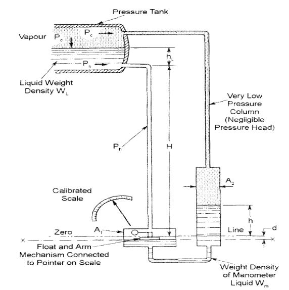
Level Measurement Manometer
A level measurement manometer is a device used to measure the level of a liquid by comparing the pressure exerted by the liquid with a reference pressure. It typically consists of a U-shaped tube filled with a liquid, where the height difference between the two arms of the tube indicates the level of the liquid being measured.
Electric and Pneumatic Level Transmission
Level-indicating devices can be connected to electrical transmitters to generate an electrical signal, which can be utilized for automated control systems or remote indications. This allows any primary measuring device that produces mechanical motion as an output to have that motion applied to a transducer for further processing.
Capacitance Level Gauge
The tank, equipped with an insulated electrode, functions as a capacitor with capacitance directly correlated to the quantity of product contained within it. An empty tank exhibits lower capacitance, while a filled tank demonstrates higher capacitance. Furthermore, this level measurement method is suitable for process temperatures up to 400 °C and process pressures up to 500 bar.
- The larger the area of the plates, the higher the capacitance.
- The closer the plates, the higher the capacitance.
- The higher the dielectric constant, the higher the capacitance.
Video: What is a Level Sensor?
Watch “What is a Level Sensor?” [9:11].
Activity: Capacitance Level Gauge
Click the arrows to view capacitance level gauges.
Multi-probe Conductivity Column
The resistance between two measuring electrodes changes by the presence or absence of a medium. In single-rod probes, the electrically conductive tank wall serves as a counter electrode.
Conductivity Probe Level Detector
A conductivity probe level detector is a device that measures the electrical conductivity of a liquid to determine its level. By analyzing the conductivity, the detector can provide accurate information about the liquid’s height or volume within a container or tank.
Activity: Conductivity Probe Level Detector
Click the arrows to view images of conductivity probe detectors.
Nuclear Level Detection
Nuclear, also known as radiometric level detection utilizes a gamma source, typically a cesium or cobalt isotope, that emits radiation. This emitted radiation is attenuated as it traverses through different materials. Level detection is based on measuring the effect of radiation absorption by the substance being measured, which occurs due to changes in the level of the substance.
Point Level Measurement
Point-level measurement involves the use of a radioactive transmitter positioned on one side of a vessel, along with a measuring cell placed on the opposite side. As the liquid level within the vessel fluctuates, the measuring cell detects changes in the intensity of beta or gamma radiation it receives. This radiation intensity alteration occurs because the liquid itself absorbs a portion of the radiation emitted by the transmitter.
Continuous Level Measurement
Continuous level measurement involves the utilization of multiple measuring cells positioned on the opposite side of the transmitter. Each measuring cell directly converts the received radiation energy into an electrical current, which is then amplified and utilized for external control or indication purposes.
Activity: Nuclear Level Measuring
Click the arrows to view the types of nuclear level measuring.
Advantages:
- The device does not require any part to be in direct contact with the measured liquid.
- It is not susceptible to damage from high temperatures, high pressures, corrosion, or issues caused by liquid viscosity.
Disadvantage:
- The need for thorough shielding of the radioactive source is essential to ensure the safety of personnel in the vicinity.
Ultrasonic Level Detection
Ultrasonic level detection operates on the principle of time-of-flight. A sensor emits ultrasonic pulses that are reflected by the surface of the medium, and the sensor detects the reflected pulses. By measuring the time it takes for the pulses to travel, the distance traveled in the empty portion of the tank can be determined. This distance is then subtracted from the overall height of the tank to obtain the level of the liquid.
Ultrasonic level detection is utilized to accurately indicate the level of a substance. It offers similar advantages as a nucleonic gauge, such as precise measurements, but without the requirement of a radiation source.
Video: Ultrasonic Sensors (Screencast)
Watch “Ultrasonic Sensors (Screencast)” [5:54].
Activity: Ultrasonic Level Detection
Click the arrows to view images of ultrasonic-level detection devices.
Automated control circuits
Pneumatic – Compressed Air
Pneumatic systems utilize compressed air as a means to generate and detect instrument signals derived from field devices. Control circuits perceive alterations in a measured quantity by observing variations in the air pressure present within a section of instrument piping or tubing.
Activity: Pneumatic Transmitter
Click the image hotspots to learn more about pneumatic transmitters.
Control Loop Symbols
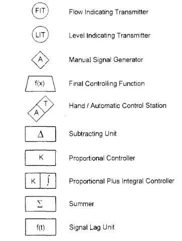
Automated Control Circuits
Automated control circuits play a vital role in digital control systems. These circuits facilitate the conversion of electrical signals into pneumatic signals, which are then used to control air-operated valves or mechanisms. Four distinct devices are commonly employed in this process:
- Current to pressure transducer, also known as an I/P converter, transforms a current signal into a corresponding pneumatic pressure signal.
- Voltage to pressure transducer, or E/P converter, converts a voltage signal into an equivalent pneumatic pressure signal.
- Pressure to current transducer, referred to as a P/I converter, changes a pressure signal into a corresponding current signal.
- Pressure to voltage transducer, known as a P/E converter, translates a pressure signal into a voltage signal with proportional characteristics.
These devices enable the seamless integration of electrical and pneumatic systems, enabling precise control and operation of air-operated valves and mechanisms in digital control systems.
Electric And Magnetic Type Level-limit Devices
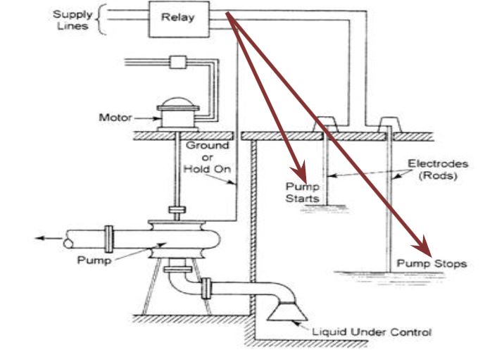
Electric and magnetic-type level-limit devices are commonly used to detect whether the liquid level in a vessel is above or below a specific point. They are employed instead of continuous level monitoring. For example, they can be utilized in a starting circuit for a pump that starts when the liquid level reaches a minimum level and shuts down when it exceeds a high level.
Start/Stop Level Control
Electrodes stop and start the pump to maintain a level in the sump.
Ball-float and Variable-displacement Devices
Ball-float and variable-displacement devices are used for level-limiting purposes because they can be incorporated to have the float open or close a limit switch or similar device.
Magnetic Level-Limit Device
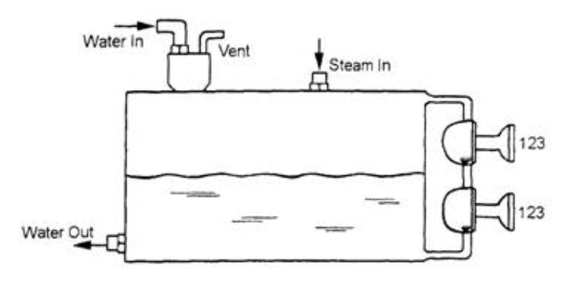
A magnetic level-limit device utilizes permanent magnets to serve dual purposes:
- limiting the liquid level
- providing level indications
This device employs specialized flakes that are color-coded, with one side red and the other side blue. The positioning of a floating magnet ensures that the flakes align in such a way that the column appears all red above the indicated liquid level and all blue below it. Thus, the magnetic level-limit device effectively indicates the level and restricts it within the desired range using the magnetic properties of the system.
Activity: Magnetic Level Limit Devices
Click the image hotspot to learn more about magnetic level limit devices.
Click the arrows to see images of magnetic level limit devices.
Connections are also made for:
- Transducers for remote indication.
- Contacts to provide high and low-level alarms or control functions with the vertical movement of the float drives.
Remote Water-level Indicators
Remote water level indicators provide a direct indication of water level without any process control or control power to operate it. Safe operation depends on maintaining a proper level even when the process controls have failed, or when the control power supply has been lost. This is particularly important for the boiler drum level.
Activity: Remote Water-level Indicator
Click the arrows to view images of remote water-level indicator.
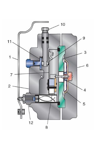
Activity: Remote Water-level Indicator Standard Parts
Click on the accordions to learn about the standard parts of the remote water-level indicator.
Note: The numbers for each accordion tab correspond to the numbers on the diagram.
Features and Benefits
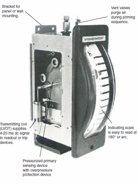
- Remote Reading: transfers hard-to-see liquid level readings from inaccessible points down to eye level.
- Continuous Indication: primary sensing device is operated by the liquid in the boiler itself.
- Foolproof: actuating diaphragm can withstand high unbalanced pressure.
- Complete: can be linked with a control module that actuates sound and light alarms.
- Density Compensation: for changes in density at various operating pressures (0 to 3,000 psi; 0 to 207 bar).
- No Mechanical Linkages: located outside the pressure zone, the indicating system receives its signal through a magnetic coupling.
Differential Pressure Level Indicator
The device utilizes a vertical diaphragm to detect the water level by measuring the differential pressure. This diaphragm is equipped with a permanent horseshoe magnet at its free end, and its motion is transmitted to a deflection plate. The housing of the device includes a non-ferrous alloy tubular well, positioned between the poles of the magnet. Inside this well, there is a spiral strip armature made of magnetic material, which is mounted on jeweled bearings. The armature, when rotated, amplifies the lateral movement of the magnet along the well. To indicate the changes in water level, the outer end of the armature is fitted with a counter-balanced pointer. As the magnet moves, the armature rotates, resulting in the movement of the pointer, providing a visual representation of the water level fluctuations in the boiler.
Use and Placement of Liquid Level Measuring Devices
Different types of devices used for measuring liquid levels include ball-float, displacement-type, and hydrostatic head devices. It is important to calibrate these devices according to the specific gravity of the liquid being measured. When dealing with high-density or high-viscosity liquids such as heavy oils or hydrocarbons, the movement of the float can be hindered due to the additional fluid friction.
