2.4 Phase Variables: Control vs. Spontaneously Initiated Breaths
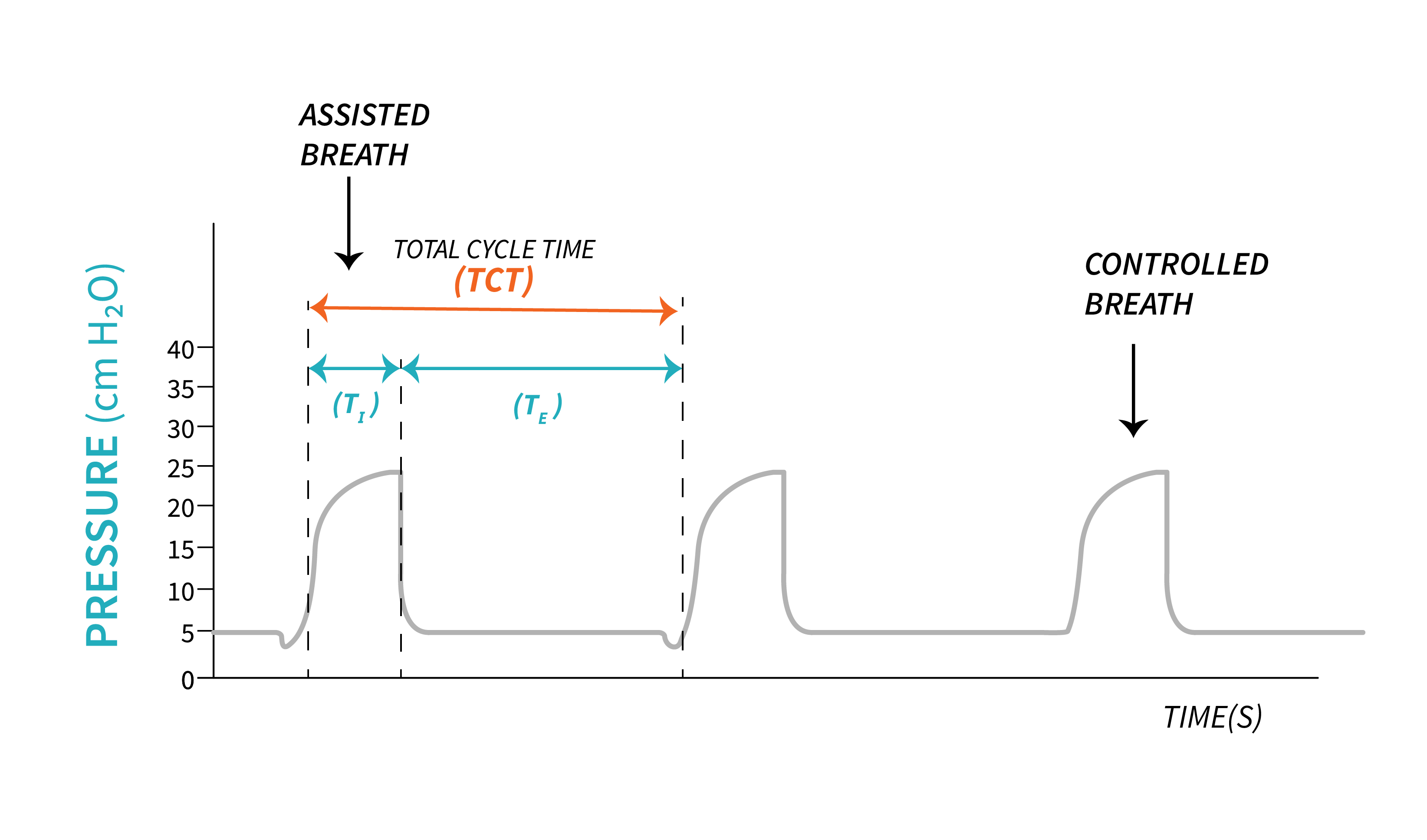
Control breaths are the breaths delivered according to the set respiratory rate on the ventilator. When we program a certain respiratory rate into the ventilator, this determines the total cycle time (Total Cycle Time, TCT). For example, if the respiratory rate is set at [latex]15\text{ bpm}[/latex], that means that there are 15 breaths that will be delivered in one minute—one every 4 seconds. Even if the patient does not have a drive to breathe, the air will still be delivered every 4 seconds. However, even in control modes, patients can choose to initiate breaths above the set respiratory rate. This means that, if the patient has their normal physiologic drive to breathe, they could initiate additional breaths as well. But if they do not, the ventilator will always deliver the set respiratory rate at a minimum.
Before we further discuss controlled and spontaneous breaths, let’s review the functions of the ventilator, and describe in detail how the ventilator enables a controlled versus a spontaneous breath.

Phase variables are parameters used by clinicians to describe and design a breath that will be delivered to the patient.

The ventilator employs distinct parameters known as variables to determine the initiation of each phase in the breathing cycle. The Trigger variable is utilized to initiate inspiration, while the Limit Variable ensures that lung distention remains within specified limits. Exhalation begins when the ventilator permits it based on the Cycle variable, and the Baseline Variable determines the level at which a new inspiration will begin.
Now, let’s explore the functions of the ventilator in relation to these phase variables.
Function |
Phase Variable |
| Initiate Inspiratory phase | Trigger |
| Stop lung distention | Limit |
| Allow exhalation | Cycle |
| Determine baseline | Baseline |
So how does a ventilator “sense” a patient?
The Trigger Variable
We have already established that positive pressure ventilation pushes air into the lungs. Microprocessors are constantly evaluating the flow of air that is leaving the ventilator and being delivered to the patient through the ventilator circuit. Recalling the process of normal physiologic breathing, think about the action of the diaphragm contracting and dropping down in the thorax. We have talked about how this movement creates a negative pressure and air will flow into the lungs. Remember that the patient is intubated and connected to the ventilator through the patient circuit. If a patient has the ability to initiate (trigger) a breath by contracting their diaphragm, his negative pressure will pull air from the circuit. The microprocessors of the ventilator are calibrated to the normal flow of air and pressure in the circuit, and even a small change with air moving into the chest is sensed by the ventilator. This is called a trigger because the ventilator senses this change and it “triggers” the delivery of the set breath.
Ventilators can be set by the respiratory therapist to sense changes through either pressure or flow. Both triggers operate in a similar way:
- A pressure trigger is activated when the contracting diaphragm decreases the overall pressure of air in the circuit.
- A flow trigger senses air being pulled from the circuit from the drop in pressure that the diaphragm creates.
Pressure or flow triggered breaths are referred to as patient triggered (assisted breaths). If the patient does not make any efforts, is unable to trigger the ventilator, breaths will be time triggered (controlled breaths) based on the respiratory rate set by the respiratory therapist.
Key Takeaway
Flow triggering is more commonly used for mechanically ventilated patients as the more comfortable trigger mechanism. It takes more effort and flow from the patient to trigger even a [latex]-1\text{ cmH}_2\text{O}[/latex] change in pressure in order for the ventilator to sense a breath request than to create a change in flow in the circuit.
Flow triggers are more commonly used on most ventilators in current practice. When the flow hits the threshold of the set flow trigger, a breath is delivered. The amount of flow that the patient needs to pull is negligible before the ventilator senses the patient initiating a breath, and then the ventilator will deliver the set breath based on the mode and settings selected. A normal flow trigger is [latex]\text{2 - 3 Lpm}[/latex]. When you think that ventilators respond in fractions of a second, even a minute change (pull of air toward the patient) triggers the breath.
As respiratory therapist, we will be able to see the changes in pressure and flow described above at the beginning of a breath by looking on the ventilator screen at the waveforms that show the delivery of the air. Reading waveforms will be discussed in detail in a later chapter, but when it comes to patients triggering breaths in control modes, you need to remember that it will cause a small negative pull in flows and pressures before the initiation of the breath on spontaneously triggered breaths. Control breaths would not have that small negative scoop before the waveform.
An easy way to see if your patient is triggering any breaths above the mandatory respiratory rate is to compare the total respiratory rate the patient is breathing against what you have set in the settings. If you set [latex]15\text{ bpm}[/latex] and you notice the patient is breathing [latex]18\text{ bpm}[/latex] in total, it is obvious that the patient is triggering breaths above the set respiratory rate.
Additionally, there are ventilation modes that grant patients greater control, enabling them to initiate breaths, determine the volume and duration of each breath. These modes allow spontaneous breaths, requiring minimal assistance from the ventilators.
Adjusting the trigger variable may require some trial and error, and it is closely linked to patient assessment. The ventilator needs to be responsive to the patient’s effort in triggering a breath while ensuring that it doesn’t add to their respiratory workload. If the sensitivity of the ventilator is set too high, it may inadvertently detect minor leaks in the circuit and trigger breaths automatically when they are not needed (auto-triggering).
The Limit Variable
Another function of the ventilator is to limit the size of a breath. This does not correlate with the end of the inspiration, but rather, how big a breath can get during inspiration. The limit variable (sometimes called the target variable) represents the maximum value that a parameter can attain. This parameter can be pressure, volume, or flow.
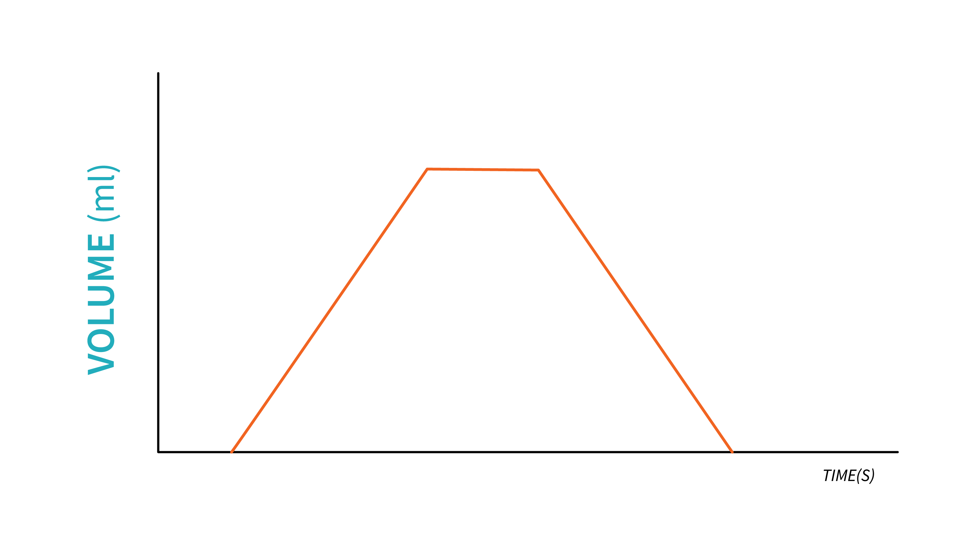
A volume limited breath is delivered by the ventilator by measuring the flow of air delivered during a specific time period. This volume will be the maximum amount of gas that will be delivered to the patient during an inspiration. Note that multiple limit variables can be set in the same time for one breath. When volume is the limit, you may notice a squaring of the volume waveform, which indicates that the maximum volume has been attained.
In a pressure limited breath, the ventilator will allow pressure to rise during inspiration up to a certain value set by the respiratory therapist. The attainment of this value does not correlate with the end of the inspiration, but rather the size of the breaths and how much air will fill the lungs to reach that pressure limit. After the limit is reached, any excess pressure entering the patient circuit, will be released though a pressure release valve.

A breath is flow limited when the gas flow into the ventilator circuit reaches the predetermined set level before the end of the inspiration. Flow limiting often leads to patient-ventilator asynchrony, when the set flow does not reach the patient’s inspiratory flow demand. Setting the flow limit requires practice with patient assessment and knowledge of physiological demands.
An important breath limiting parameter that is worth mentioning here is the Maximum Safety Pressure. This limit variable is different than pressure limit. All ventilators will have this feature for the purpose of protecting the patient’s lungs from damage caused by excessive pressure. Most ventilators will end inspiration and initiate expiration when this Maximum Safety Pressure is reached.
Example: Maximum Safety Pressure
Let’s assume the Maximum Safety Pressure is set to [latex]40\text{ cmH}_2\text{O}[/latex]. When volume is set as the limit variable, and the pressure required to deliver the set volume reached [latex]40\text{ cmH}_2\text{O}[/latex], the ventilator will end inspiration, allow the exhalation valve to open and release the air.
The Cycle Variable
The Cycle variable is used to determine the opening of the exhalation valve and end inspiration. Only one parameter is used at a given time, and it can be one of the four: volume, pressure, flow, and time.
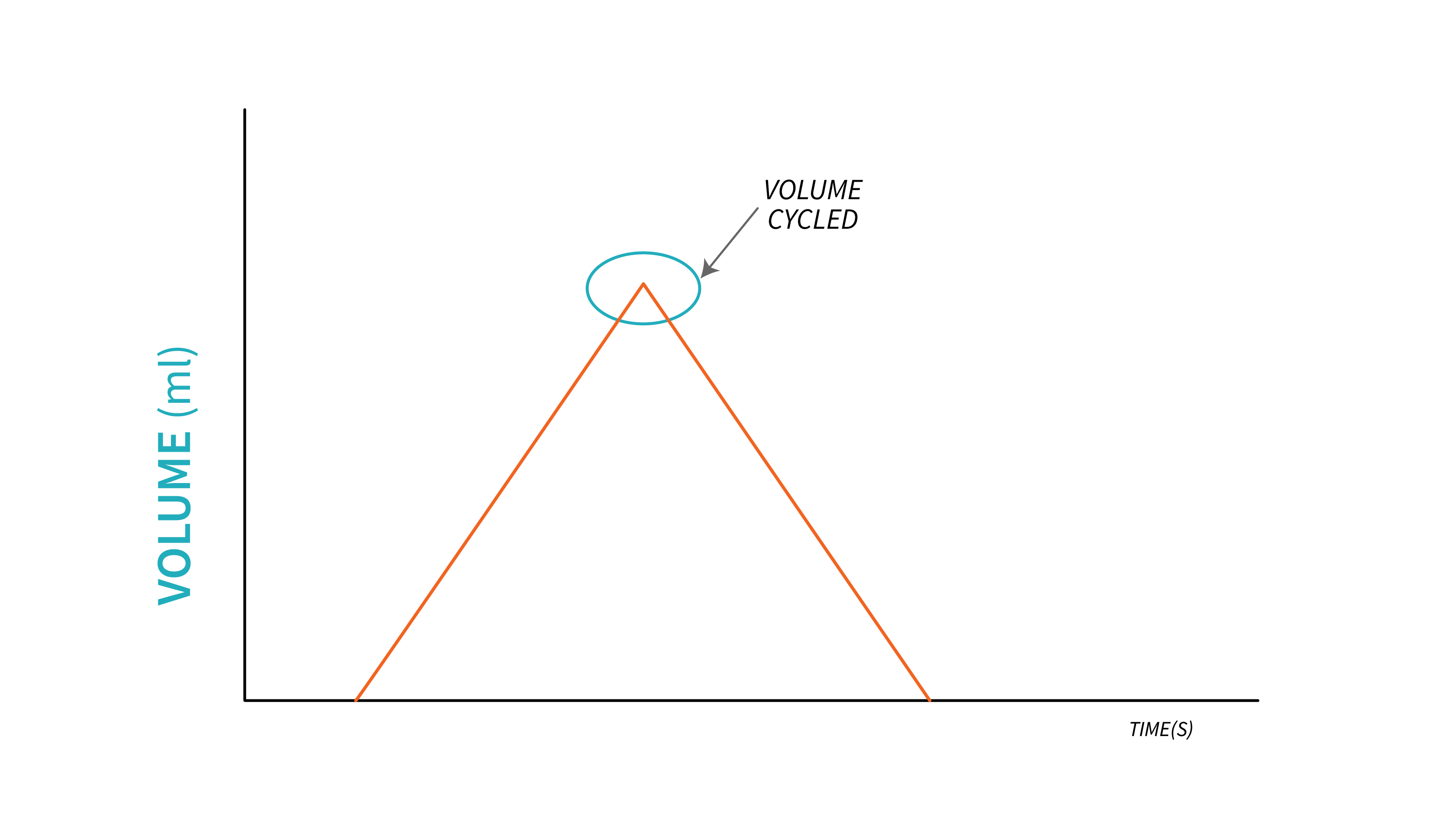
During a volume cycled breath, inspiration stops, and we say that the ventilator cycles into exhalation once the target volume is delivered. This may be a problem when lung mechanics change. This is when the limit variable and maximum safety pressure play a crucial role. If the ventilator is programmed to deliver the target volume regardless of alterations in lung mechanics, excessive pressure may be necessary to achieve that volume. Without an appropriate pressure limit, the pressure delivered to the lungs can escalate to unsafe levels. This inherent drawback of volume cycling, related to safety, is one example of why this cycling mechanism is not frequently used.
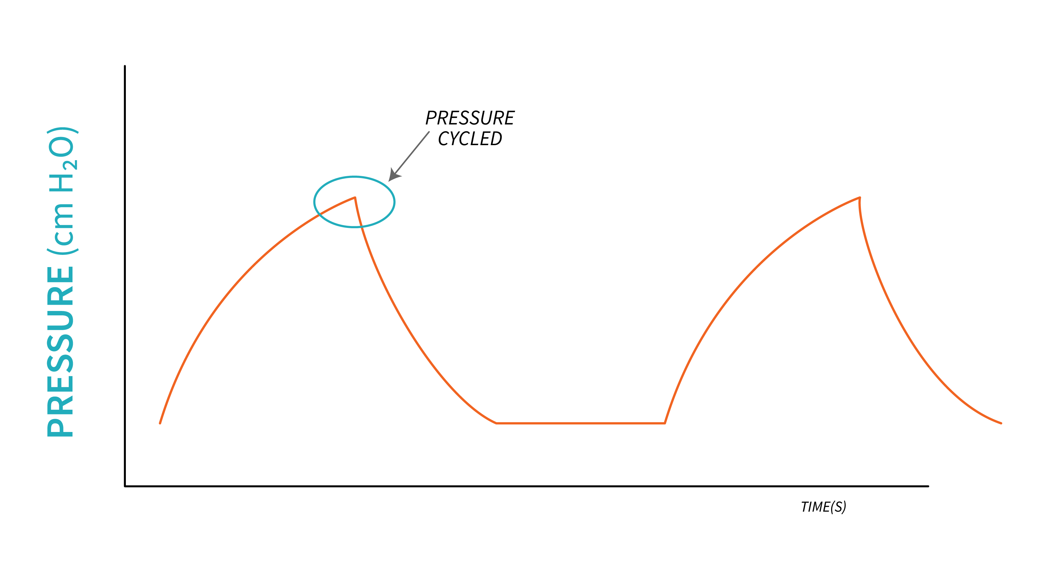
During a Pressure cycled breath, inspiration stops when a certain preset pressure is achieved. This signals the ventilator to open the exhalation valve and allow air to flow out of the lungs. The tidal volume delivered to the lungs depends on the preset pressure, duration of inspiration, flow delivered and patient’s lung mechanics. This cycling mechanism is sometimes seen during volume limited breaths when the pressure in the lungs exceeds the maximum safety pressure. In this case, the ventilator will end inspiration in order to protect the lung from high pressure damage, and tidal volume is not delivered.
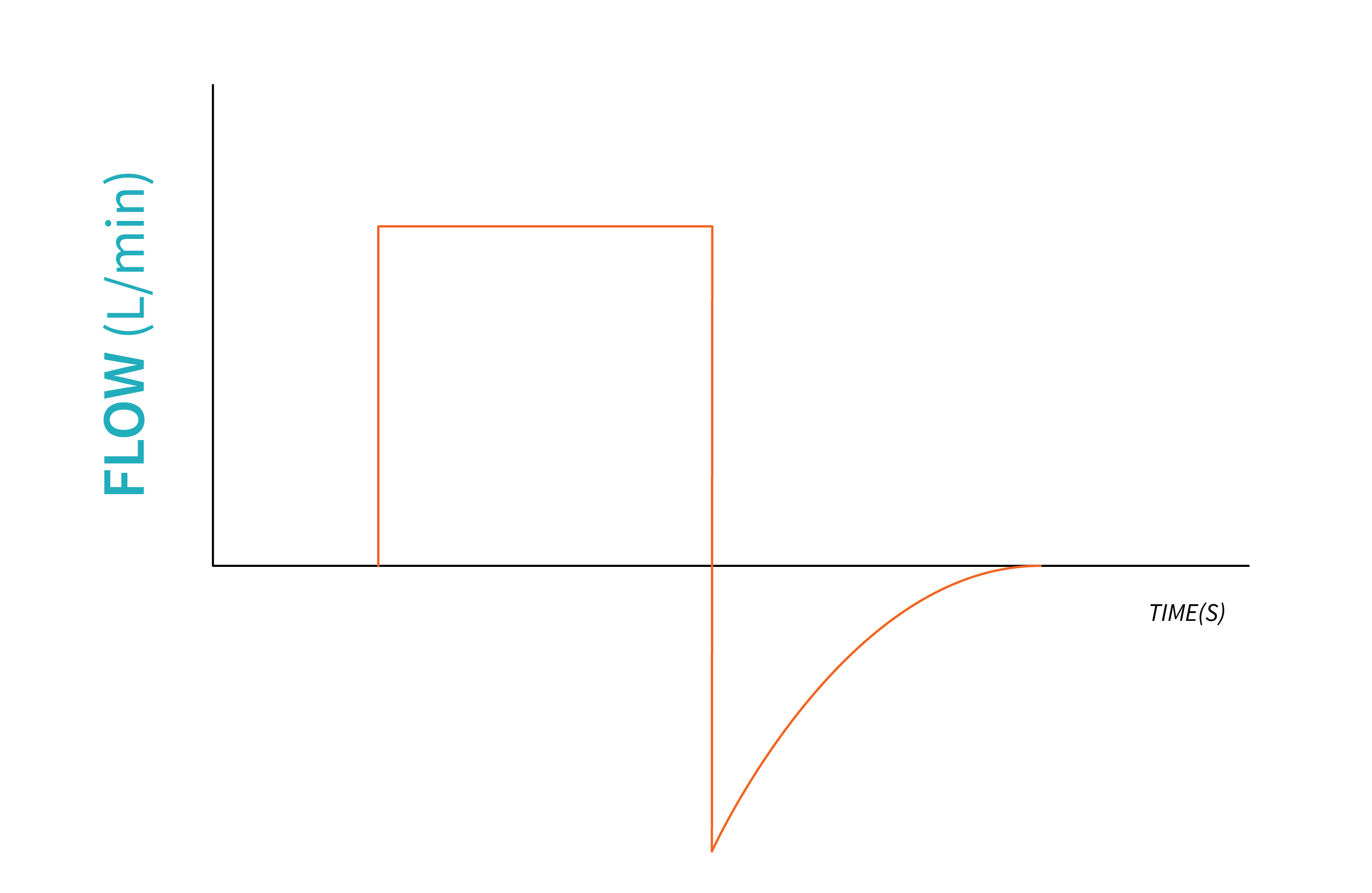
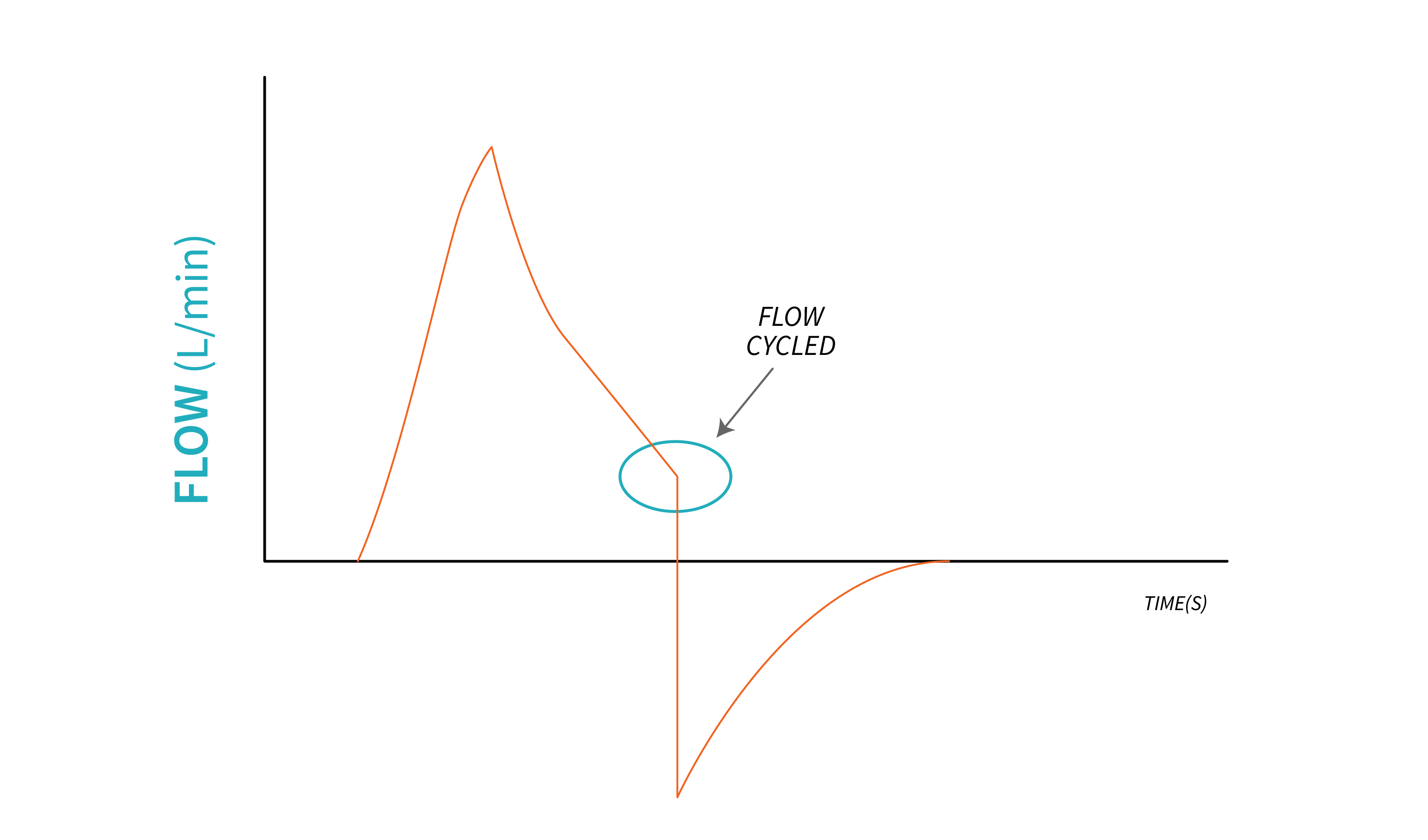
During a Flow cycled breath, the ventilator opens the exhalation valve and initiates exhalation when inspiratory flow drops to a certain level, preset by the respiratory therapist. As inspiration starts, flow increases exponentially to reach a certain inspiratory pressure. As the lungs fill with air, flowrate decreases. When it reaches a certain level (usually a percentage of the peak inspiratory flowrate), exhalation starts.
Example
Peak Inspiratory flow: [latex]80\text{ Lpm}[/latex].
Ventilator cycle signal is set at [latex]25\%[/latex] of the peak inspiratory flow. This means that the ventilator initiates expiration when inspiratory flow drops to [latex]25\%[/latex] of [latex]80\text{ Lpm}[/latex] (at [latex]20\text{ Lpm}[/latex]).
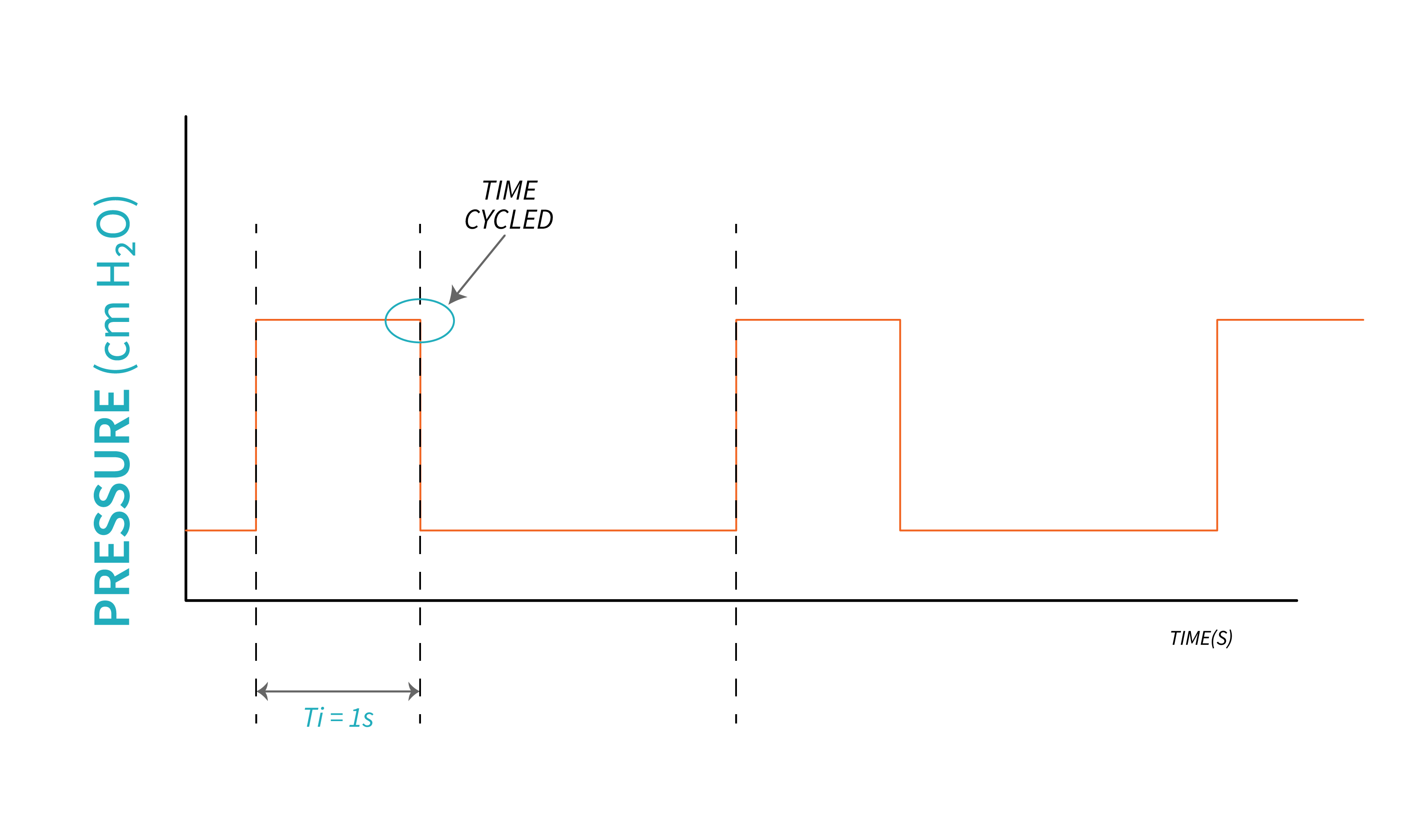
In a time cycled breath, inspiration ceases upon reaching a specific time interval, which is typically observed in controlled, mandatory breaths where the Inspiratory time is predetermined. The ventilator permits exhalation once the inspiratory time has elapsed, and this cycling mechanism remains unaffected by alterations in lung mechanics.
The Baseline Variable
This variable describes the expiratory phase and it is usually based on the pressure exerted by the volume left in the lungs during expiration. As previously discussed, this is represented by positive end expiratory pressure, PEEP. All breaths will start from PEEP level and end at the same level. For healthy lungs, a PEEP of [latex]5\text{ - }8\text{ cmH}_2\text{O}[/latex] is usually selected as baseline. For low compliant lung (such as in ARDS), a higher PEEP will be used, and in some cases a baseline of zero is used.
It is important to monitor the return of airflow to its baseline during each breath because inadequate time for expiration can lead to air trapping, resulting in intrinsic PEEP (auto PEEP).
“Control vs. Spontaneously Initiated Breaths” from Basic Principles of Mechanical Ventilation by Melody Bishop, © Sault College is licensed under a Creative Commons Attribution-NonCommercial-ShareAlike 4.0 International License, except where otherwise noted.
