2.1 Ventilators: The Basics
Types of Ventilators
A mechanical ventilator can be described as a device that aids or takes over a patient’s breathing. Essentially, a ventilator can be thought of as a computerized machine capable of generating airflow. There are three different types of devices that can perform this function: negative pressure ventilators, positive pressure ventilators and high frequency ventilators.
Negative Pressure Ventilators
Negative pressure ventilation mimics physiological breathing. The most known example of negative pressure ventilator is the Iron Lung (Figure 2.1.1).
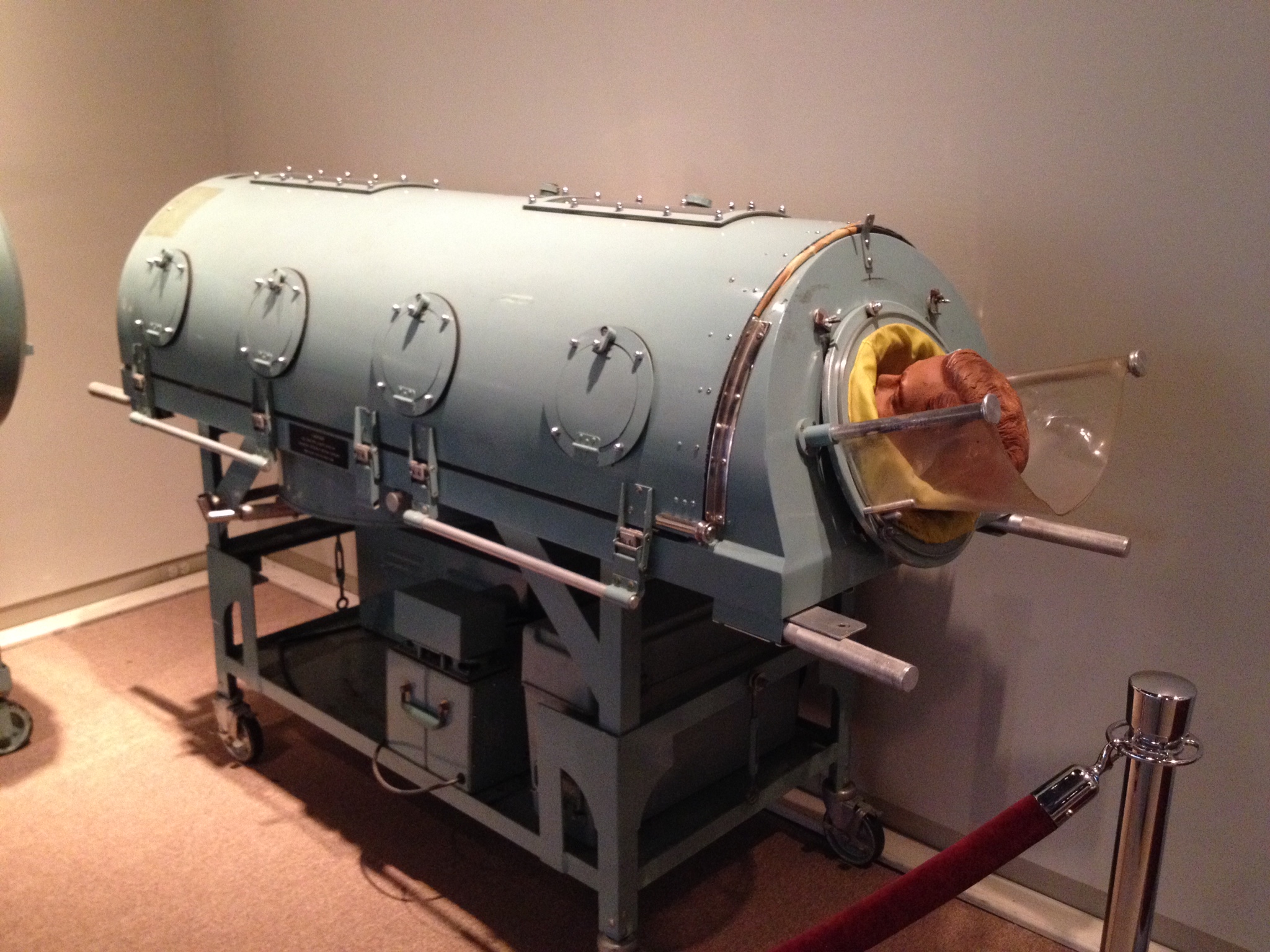
The patient’s entire body, including the thorax, is enclosed in an airtight container, with sub atmospheric pressure [latex](\text{P}<0\text{ cmH}_2\text{O})[/latex]. The patient’s head is exposed to atmospheric pressure [latex](\text{P}=0\text{ cmH}_2\text{O})[/latex]. A negative pressure ventilator, operates by creating negative pressure or vacuum around the patient’s chest or body. Instead of pushing air into the lungs like a positive pressure ventilator, a negative pressure ventilator gently pulls or draws air out of the lungs. The negative pressure generated around the patient’s thorax, is transmitted to the pleural space and consecutively to the alveoli. This creates a pressure differential, causing the chest to expand and allowing air to flow into the lungs naturally. Negative pressure ventilation closely resembles physiological breathing. Expiration occurs passively due to the normal elastic recoil of the lungs and chest wall, when the negative pressure around the thorax is removed.
Object Lesson
During negative pressure ventilation, inspiration occurs when negative pressure is applied to the chest, transmitted to pleural space and alveoli, creating a pressure gradient that allows airflow into the lungs (Remember, air flows down a gradient from high pressure to low pressure).
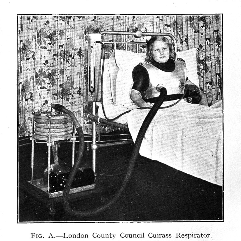
Another type of negative pressure ventilation is the chest cuirass (Figure 2.1.2).
Negative pressure ventilation is less commonly used compared to positive pressure ventilation and is often employed in specialized cases or certain conditions where positive pressure ventilation may not be suitable.
Positive Pressure Ventilators

Positive pressure ventilation requires the use of a device that is capable of generating airflow and creating pressure that is greater than atmospheric pressure. In simple terms, this is a machine that will push air into the patient’s lungs by creating a pressure gradient between airway opening and alveoli. To perform this function safely, the following elements are required: power source – power conversion and transmission system- control system and output system, with alarms for every one of these systems. The main functions of the ventilator can be described as four phases: initiation of inspiration, limitation of inspiration (stop lung inflation), allow exhalation and determine baseline.

1. Power Source:
A reliable power source is necessary for adequate function. Ventilators can be electrically powered, pneumatically powered or both.
Electrically Powered Ventilators
Electrically powered ventilators are designed to operate on electricity from the main power supply of the facility with a backup battery option for uninterrupted use during power outages or when transporting the patient.
Pneumatically Powered Ventilators
Pneumatically powered ventilators require a source of pressurized gas, usually oxygen or air, at a pressure of [latex]50\text{ psi}[/latex]. This gas source can be an integrated compressor or a connection to an external oxygen and/or air supply.
A special pneumatically powered ventilator is a fluidic ventilator. It operates based on fluid dynamics principles rather than traditional mechanical mechanisms. This type of ventilator is used in specific clinical situations where conventional mechanical ventilators may not be suitable or available.
Most ICU ventilators we currently use require both electrical and pneumatical power source, and are microprocessor controlled. Two [latex]50\text{ psi}[/latex] provide power to generate gas flow, while electricity powers a microprocessor and various valves are powered electrically that control the pattern and direction of flow.
2. Power conversion and transmission:
This part of the ventilator is made up by the drive mechanism and the output control mechanism, and it generates and delivers pressurized gas. The drive mechanism achieves this through a variety of methods, including direct application of high pressure gas, though a pressure reducing valve, through mechanical fans or turbines, compressed gas sources, or a combination of both. The flow of gas generated, is then directed towards the patient via the output control valve. Examples of output control valves: diaphragm, electromagnetic plunger, proportional solenoid valves. Detailed description of various types of drive mechanisms and output control valves are available in respiratory therapy equipment textbooks.
3. Control system:
This component of the ventilator plays a crucial role in precisely regulating the pressure, volume, and flow directed towards the patient. The control system not only measures these parameters, but also governs the functionality of the exhalation valve. Essentially, it acts as the decision-making system of the ventilator, using a combination of pneumatic and electronic devices. While older references may include mechanical components in the control system, they now remain relics of the past, primarily found within the pages of historical accounts. Nowadays, ventilators rely on microprocessor control using technology for advanced and precise ventilation management. Ventilator control systems can use open-loop (also called unintelligent) or closed-loop (intelligent) feedback systems.

Open loop system refers to a ventilator that is only able to deliver a set amount of gas to the patient as programmed by the respiratory therapist without the ability to adjust or sense the actual outcome (unable to recognize potential leaks or other changes). Imagine a barista pouring coffee into a mug based on open-loop feedback type instructions. The barista will pour the entire carafe of coffee into the mug without considering whether it exceeds the mug’s capacity. As a result, the excess coffee spills over the edges being wasted and ending up on the kitchen counter (Figure 2.1.5).
A closed loop system refers to a ventilator that can deliver a predetermined volume or amount of gas to the patient’s lungs, measure the exhaled volume by the patient, compare the delivered and exhaled volumes, and then make adjustments to the ventilation parameters based on this comparison. The goal is to adapt the delivery of gas to optimize patient outcomes and maintain appropriate ventilation. The control system of the ventilator monitors and adjusts ventilation parameters as programmed by respiratory therapists on the user interface (control panel). Examples of these parameters include tidal volume, respiratory rate, inspiratory-to-expiratory ratio, and positive end-expiratory pressure.
The pneumatic circuit is made up by a series of tubes that direct gas flow to the patient. There are two components of the pneumatic circuit: internal and external. The internal circuit directs gas flow from the power source to the external circuit. A simplified schematic of a ventilator circuit is illustrated below. For details on specifics of ventilator circuits and components, please refer to manufacturer information packages.
The external circuit consists of tubing that carries the gas flow from the ventilator to the patient and may include additional components like filters, humidifiers, and heat exchangers to optimize patient comfort. The circuit tubing is generally corrugated plastic (22 mm inside diameter for adults), which has universal connectors ([latex]22\text{ mm}[/latex] outside diameter, [latex]15\text{ mm}[/latex] inside diameter) that connects the ventilator to the endotracheal tube (ETT), tracheostomy tube, or noninvasive interface.
Plastic circuits used for conventional ventilation will have a certain compliance and resistance, that must be taken into consideration.
Circuit Compliance
When the ventilator generates pressure in the circuit, the plastic material will allow for expansion, due to its compliance (this is often seen as movement, as the circuit tends to straighten during inspiration). This tubing compliance represents the volume of gas compressed in the circuit for every cmH2O of pressure generated by the ventilator. Because of this, some of the volume delivered will be lost (or trapped) in the corrugated circuit during inspiration. During expiration, this volume of gas leaves the circuit through the exhalation valve.
The volume lost in the circuit due to tubing compliance is referred to as compressible volume. Most ventilators have the ability to determine and make adjustments, so that the compressible volume does not significantly affect patient ventilation.
Circuit Resistance
Plastic tubing used with most ventilators is usually wide enough in diameter to minimize resistance to flow. The resistance to flow through a typical ventilator circuit generates a pressure of less than [latex]0.5\text{ cmH}_2\text{O}[/latex] at [latex]30\text{ L/min}[/latex] flow rate. Ventilators have the ability to determine and account for circuit resistance. It is important to note that any addition to the length of the circuit, must be taken into consideration by the respiratory therapist. For example, adding length to the circuit for transport purpose may increase resistance. Another example is adding inspiratory or expiratory filters that may become saturated when high humidity is used, increasing resistance in the circuit (Figure 2.1.7).

The Exhalation Valve
The purpose of the exhalation valve is to close the circuit during inspiration so that air flow is directed towards the patient’s lungs, and open during expiration, to allow air flow to leave the patient’s lungs. This valve allows for unrestricted flow from the patient, or it can increase resistance to flow, in order to maintain an elevated baseline with positive pressure at the end of exhalation (PEEP). Exhalation valves are often flow or threshold resistors, spring loaded valves, diaphragm valves, magnetic and electromagnetic valves. Details on these devices can be found on respiratory therapy equipment textbooks.
Floating Exhalation Valve
The traditional mechanism of operation of exhalation valve allows it to open when exhalation starts, or if pressure in the circuit exceeds the upper pressure limit set by the respiratory therapist. A floating exhalation valve, sometimes called active exhalation valve, is designed to provide more precise control over the exhalation process and improve ventilation efficiency. The microprocessor in the ventilator actively regulates this valve to release of excess expired air when pressure builds up in the circuit. It responds to changes in pressure within the patient’s lungs and adjusts the valve opening accordingly. This allows for better synchronization between the patient’s breathing pattern and the ventilator’s support. The main advantage of a floating exhalation valve is its ability to optimize ventilation by adjusting the resistance to exhalation based on the patient’s needs.
