39 Transient Response of Thermal Systems
We will look at several practical examples where the measured temperature is different from the temperature of the material we care about, and where it takes time for the measured temperature to respond to changes. A sensor on the wall of a coffee cup won’t read the temperature of the coffee in the cup, even though it will give us useful information.
Equilibrium Sensor Temperature
At equilibrium between the coffee inside the cup and the air on the outside, the temperature reached by the sensor on the wall will be somewhere in between, governed by heat transfer and an energy balance. (video 6:23)
The sensor will reach a temperature somewhere between the ambient and the coffee cup it’s attached to. We can define a Coffee Index as an indicator of where the sensor temperature sits between them.
CI = (Ts – Ta) / (Tc – Ta)
The Coffee Index (CI) will approach 1 if the sensor is really close to the coffee temperature and 0 if it is really close to ambient temperature. A CI of 0.5 would put it right in the middle. What kind of attachement would get the CI closest to 1? Could you calibrate your system and then use your sketch to adjust the estimated coffee temperature based on the calibrated CI?
Sensor Transient Response to Step Function Change
Watch the video (11:45) for a detailed explanation of the transient temperature response to a step function change in surroundings. The result of a heat balance is an exponential decay towards the new temperature of the surroundings with a time constant depending on the physical details of both the sensor and the surroundings. For faster response you need to make the sensor smaller to lower the mass and increase the heat transfer coefficient by better thermal contact or faster moving fluid in the surroundings.
We can get a reasonable solution numerically using Euler’s method.
Thermal System Response – will the temperature be well controlled?
The same heat balance approach with Euler’s method can track the changes in temperature of multiple elements in a system whether it’s a coffee cup or a 3D printer nozzle assembly or build plate. A spreadsheet or a Jupyter notebook allows simple calculations of time response. (video 11:10)
This transient system is for a heated coffee cup, but the same approach will apply to the transient performance of the heated bed in a 3D printer, or the time variation of the room temperature when a space heater is controlled by an on/off thermostat.
Transients in a 3D Printer Nozzle Assembly

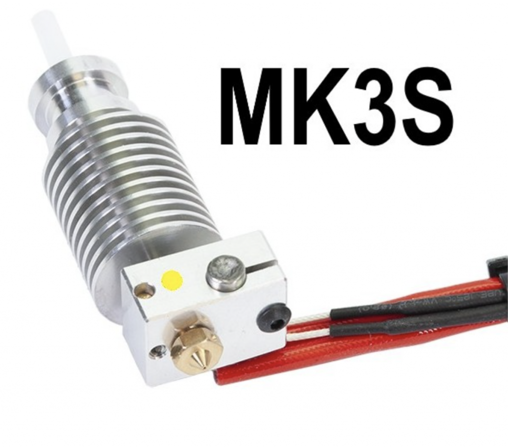
With no power applied, all the components in this assembly will be at ambient room temperature. When it’s time to print, the microcontroller will apply electric current to the heater clamped in the aluminum block. The heater will warm the block and the brass nozzle, which will in turn warm the thermistor embedded in the bock with silicone. During this heating phase, the heater will always be hotter than the block, which will in turn be hotter than the sensor.
The objective of a good control strategy would be to heat the nozzle quickly to the desired target temperature, then hold it steady at that temperature until the print run is over. If the sensor is slower than the heating process, it may be difficult to avoid overheating or oscillations in temperature which could reduce the quality of the end product.
The Prusa printer uses PID (proportional, integral, differential) control to provide good performance and closely follows the target temperature while printing, after a brief warm-up transient. We can simulate the behaviour of this simple system directly on our microcontroller to see the effects of different approaches in real time. (Video 12:04)

