30 Analog Output and Switching Circuits
Analog Output Circuits
Sometimes a PWM output using analogWrite() is enough to control things like the speed of a DC motor or the perceived brightness of an LED light. For other applications you may need a continuous DC output voltage. If your microcontroller supports a true Digital to Analog Converter (DAC), then you can get values from 0 to  simply using analogWrite() to a DAC pin. But what if you only have PWM, or if you want a voltage larger than ?
Smoothing PWM output
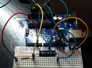
Reach back and remember RC circuits and time constants. Connect a resistor to the PWM output (red wire). Connect a capacitor (crimped end positive) from the resistor to ground (green wire). Measure the voltage where the capacitor and the resistor meet (yellow wire) with a high impedance device like an analog input, oscilloscope, or multi-meter.
The time constant  is in microseconds if the resistance is in Ohms and the capacitance is in microFarads, so a 10K resistor and a 33uF capacitor gives
  or about a third of a second for really smooth transitions. Switching down to a 2.2 uF makes it 22 ms which follows human scale pretty well while still averaging over many PWM cycles. The graph below shows results for different resistor and capacitor combinations. The direct connection seems to have its frequency response compromised by the other circuits. The 2.2 ms yellow squares are noisy, while the 33 ms red exes and 47 ms triangles respond quickly, yet follow closely. The 330 ms grey diamonds lag substantially. The sampling rate wasn’t high enough to resolve the PWM, so connecting the dots would give an aliased apparent oscillation frequency.

Drawing any significant current from this RC circuit will change the response, so it can only be directly connected to a high impedance circuit, like an amplifier or a measurement device.
Following the voltage with an Op-Amp
To drive another circuit with the analog output, use an op-amp as a voltage follower or buffer amplifier. If you need the output voltage to be higher than  , use a closed loop non-inverting amplifier circuit.
If you use the venerable 741 op amp you will need a power supply that goes well above and below (min +/-10 V specified) your desired output range. Using a rail to rail op amp like one of the TLV246x family will help you avoid that problem.
Switching Circuits
Often you need to switch an electric circuit on and off under control of your Arduino. A micro-controller can only manage small voltages and currents, so you will need additional components for any significant loads.
Switching DC with an NPN Transistor
An NPN transistor like this PN2222 can be used to switch a DC load up to about 500 mA continuous or 1 A peak. This tutorial provides a detailed recipe for controlling a small motor.
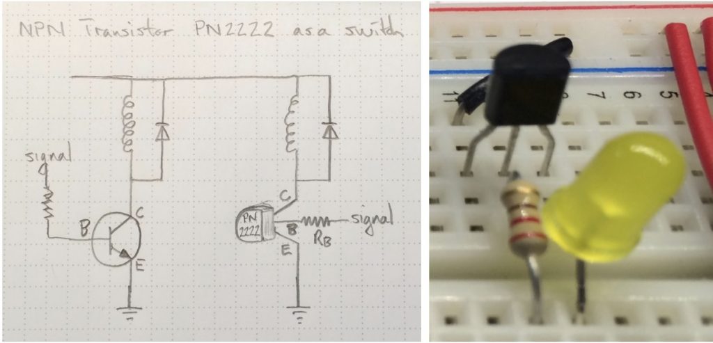
The photo above shows the small and cheap PN2222 (about 25 cents in small quantities). The yellow LED is connected as the load to the collector on the right hand pin, while the signal is connected to the base on the middle pin, through a current limiting 220 ohm resistor. The left hand emitter pin is connected to ground through the black wire in behind.
The current gain on the PN2222 transistor varies from 35 to 300, depending on the conditions, so the collector emitter current will always be up to 35 times as high as the base emitter current. The voltage drop from base to emitter will be between 0.6 and 2 volts, so the voltage drop across the resistor (220 ohm) on the base will be at least 3 volts for a 5 volt signal. By Ohm’s Law the current will then be at least 13.6 mA, allowing a current of at least 13.6 x 35 = 476 mA to flow through the load and the collector emitter path through the transistor.
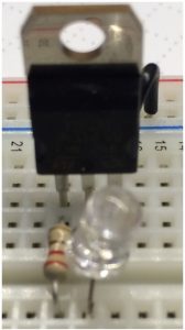
You can use the same approach with a Darlington transistor (about $1 each in small quantities) to handle somewhat higher currents without going to the full expense of a MOSFET. Note that the pin arrangement is different between the Darlington at right (signal, load, ground to base, collector, emitter, left to right) and the PN2222 above.
Switching DC with a MOSFET
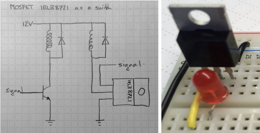
This bildr blog entry shows how to use an N Channel MOSFET (about $2 each in small quantities) as a DC switch you can control with your arduino output. I used an IRLB8721 which is good for up to 62 amps of low voltage current at room temperature. This MOSFET switching approach is overkill for low currents, and you could use a lighter duty switching transistor to save cost and bulk.
Keep in mind that you can use PWM on the signal to get the same effect — dimmer light or lower motor speeds — as using a lower analog voltage.
The heat sink plate is directly connected to the drain pin, so accidentally grounding it will allow current to flow through the load, basically switching on. If you need to switch on the positive side of the load, you should consider a P channel MOSFET instead of the N channel. The N channel, low side configuration shown here is preferred for simplicity and the low DS resistance in the “on” condition — resulting in lower power losses and less heat to dissipate.
The diagram shows an inductive load like a motor, complete with a flyback diode to avoid voltage spikes when you switch the load off. A 1N4001 is good for an average of 1 A with peaks as high as 30 A now and then. For simple on/off you can probably get away with the peak rating, but PWM keeps switching on and off at high frequency so the average rating would be a better limit. For better switching of DC motors, buy a complete H-bridge motor driver or controller.
If your load is a brushed DC motor, you probably want a small ceramic capacitor connected right across the motor along with the diode to reduce brush contact RF noise from sparking. You will also want a much bigger electrolytic capacitor from the power supply positive to ground to avoid disrupting the ground your motor circuit shares with your micro-controller. For significant motor currents, that packaged H-bridge motor driver probably has the power capacitor question better sorted out, like this 30 Amp Peak Pololu Driver that provides room for 2 or 3 capacitors in the 330 uF range.
Switching AC Loads with an SSR
Don’t even think of wiring up AC circuits unless you have the training and skills to do so safely.
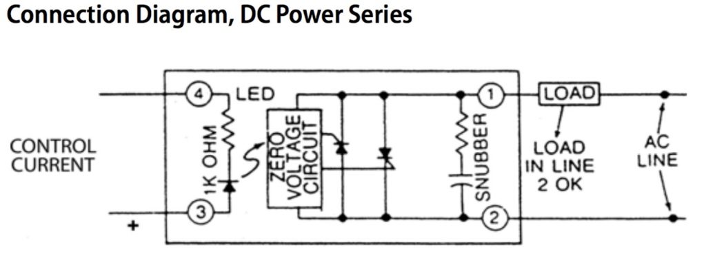
Solid State Relays are just what they sound like. They use solid state switching circuits instead of the electro-mechanical contact switching in a traditional relay. The circuits follow the AC voltage to allow them to switch only when the voltage is crossing zero. They provide complete isolation of your Arduino control signal circuit from the potentially damaging and dangerous AC current.
The LED in the circuit between pins 3 and 4 emits light when there is a positive drive voltage. That light is detected by the Zero Voltage Circuit on the AC side as a signal to switch the high voltage AC circuit, so there is no electrical contact between them.
SSRs can switch rapidly with no moving parts, however they add some resistance to the circuit even when switched on, reducing the efficiency of the operation. Be cautious about counterfeit SSRs that may work, but not meet rated power capabilities.
All you really need to know is that switching a household voltage AC circuit on and off under software control is as simple as turning on the LED inside an optically isolated solid state relay (SSR), so watch this: (video 1:30)
Application Example: Controlling a Fridge with an SSR
My fridge was generating noise in the background of my videos. Here’s the circuit I used to shut it off temporarily and the Arduino code to control it. Don’t try this unless you have the skills to do it safely and be sure to follow your local electrical code. (video 7:32)
The fridge switch got more complicated when I tried to use a more computationally powerful micro-controller to implement the same capabilities. The driving strength of the M0 processor is under software control and may not be high enough to operate some output devices. This advanced case study is a good example of troubleshooting and problem solving in a practical application. It will be especially useful for grad students working on IOT projects. (video 14:50)
Media Attributions
- Circuit PWM DAC RC UNO © Rick Sellens is licensed under a CC BY (Attribution) license
- Circuit PWM DAC RC UNO Response © Rick Sellens is licensed under a CC BY (Attribution) license
- Switch NPN © Rick Sellens is licensed under a CC BY-SA (Attribution ShareAlike) license
- Switch Darlington © Rick Sellens is licensed under a CC BY-SA (Attribution ShareAlike) license
- Switch MOSFET © Rick Sellens is licensed under a CC BY-SA (Attribution ShareAlike) license
- Switch SSR © Opto 22 adapted by Rick Sellens is licensed under a All Rights Reserved license
