32 Sensors
This chapter covers a very small selection of sensors as examples to give you a starting point. The best source of sensor information is always the manufacturer’s latest data sheet!
Bosch Pressure and Environmental Sensors
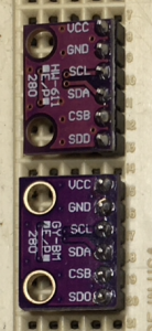 This family of sensors is evolving rapidly, adding new measurement capabilities, reducing power consumption and weight, on a more or less annual basis. Inexpensive (~$2) breakout boards from eBay like those at the right can be difficult to differentiate. One of those is a BMP280 while the other is a BME280. The I2C address also varies depending on the source of the board. Hook up your I2C devices to power (VCC), ground (GND), SCL, and SDA, then run my I2C scan code to get output like this:
I2C device found at address 0x77 Found a BMP/BME Sensor ID = 0x55 at address 0x77 BMP085/BMP180=0x55, BMP280=0x56-0x58, BME280=0x60, BME680=0x61BMP 180 for Pressure and Temperature
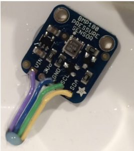
The Bosch BMP 180 (check the data sheet [Bosch breaks these links almost every year – Google is your friend]) provides highly accurate measurements of absolute atmospheric pressure at a price low enough for incorporation in many consumer products. It has all the circuitry and processing on board to measure the pressure, convert it to a digital value in Pascals (Pa), and communicate that digital value over an I2C interface commonly used in microcontrollers like the Arduino and supported by the wire library. We will use a breakout board from Adafruit that makes it easier to connect to the chip and use their library software so we don’t need to learn the details of I2C and Wire unless you want to. Download and install the Adafruit libraries as described in this tutorial. You’ll know you got the installation right if the sample code from the tutorial will compile, but you won’t be able to see actual results until you hook up a pressure transducer in the lab.
This transducer went into phones and other consumer applications in large quantities around 2014 and has now been superseded by the BMP 280, BME 280, and BME 680, which may explain why BMP180 breakouts from Asian sources were available very cheaply in 2016/2017. Bosch has indicated that this sensor has reached end of life and should not be included in new designs.
Connect the SDA lead (yellow in this photo) to SDA on the microcontroller (UNO pin A4) and the SCL lead (green in this photo) to SCL on the microcontroller (UNO pin A5) and run the example code at Adafruit BMP085 Unified/sensorapi to collect data from the sensor.
BME 280 for Pressure, Temperature, and Humidity
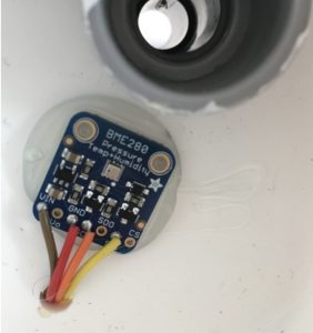
The Bosch BME280 (data sheet) provides atmospheric pressure, temperature and humidity over either I2C or SPI, both commonly used by micro-controllers. This breakout board from Adafruit makes it easier to connect to the chip and use their library software. Download and install the Adafruit libraries as described in this tutorial. You’ll know you got the installation right if the sample code from the tutorial will compile, but you won’t be able to see actual results until you hook up a pressure transducer in the lab.
This transducer supersedes the BMP 180 and BMP 280 to provide more capabilities at a similar price point. It will not work with the BMP180 or BMP280 libraries!
Connect the SDI lead (yellow in this photo) to SDA (UNO pin A4) and the SCK lead (orange in this photo) to SCA (UNO pin A5) and run the example code at Adafruit BME280/bme280test to collect data from the sensor. (Note that the leads are labelled to match the SPI interface, but when running in I2C mode SDI=SDA and SCK=SCL)
OMEGA PX137 Differential Pressure Transducers
Differential pressure sensors directly measure the difference between two pressures applied to separate inputs.
In fluid flow it is often the difference between two pressures that is important in determining forces, velocities, flow rates, etc., as you find out in MECH 241. A differential pressure transducer can easily measure gauge pressure (the difference between the input and atmospheric pressure) by leaving one of the ports open to the ambient air.
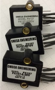
The PX 137 differential pressure transducer from Omega is available in various measurement ranges. Their web site says “The PX137 Series pressure transducers use state-of-the-art micro-machined silicon pressure sensors in conjunction with stress-free packaging techniques to provide highly accurate, temperature-compensated pressure measurements for the most demanding applications.” They don’t tell us anything more about what’s inside the box, but I’m guessing they have a silicon diaphragm that deflects one way or the other based on applied pressure, similar to these chips from Freescale designed for microcontroller applications. When the diaphragm bends, the resistance of strain gauge elements on the diaphragm changes in a bridge circuit just like the one you used for your load cells.
We are using the PX 137 because we already had some, although we might make a different choice if we were buying new sensors. Although the PX 137 is rated for supply power at 12 volts, we are going to see if we can measure adequately using a supply power of only 5 volts. Like the load cell, the output voltage is at the millivolt level, so we will need some amplification of the analog signal.
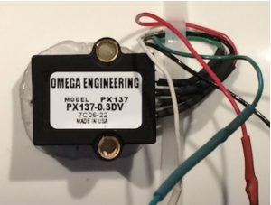
Many of the MECH 217 test rigs use this version. The “0.3DV” in the model number means the range is 0 to 0.3 pounds per square inch [psi], making it the most sensitive transducer in the range.
If you get one of the other models your measurements will work fine, and you will get different output voltages, requiring different gain choices for your amplification. Don’t be surprised when you need to choose a different gain resistor than your neighbours.
Thermocouples
Thermocouples come in a variety of standard types, sensing temperature based on junctions of different dissimilar metals, ranging from inexpensive alloys of Copper and Iron to more exotic combinations including metals like Platinum, Tungsten, and Rhodium.
Type K Thermocouples
Manufacturer’s Reference Page: http://www.omega.com/thermocouples.html
Type K Thermocouple Table: https://www.omega.com/temperature/Z/pdf/z204-206.pdf
Polynomial Fits to Tables: https://www.omega.com/temperature/Z/pdf/z198-201.pdf
Python Library for Thermocouples: https://pypi.org/project/thermocouples_reference/
Example: Resources-CC/Python CodeFragments/Learning Sequence/8.1.1 Thermocouples.ipynb
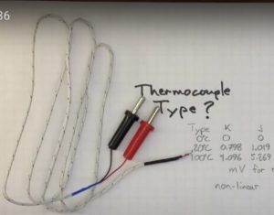
Thermocouples provide small output voltages that need amplification and cold junction correction, either manually using tables, or with polynomial fits that allow you to do the same calculations automatically in code or a spreadsheet. The python library provides an implementation of the fits to the tables and good reference information on the sources.
Type K thermocouples develop a voltage of around 4 mV per 100C, but much more when exposed to a flame. (video 3:17)
Reading Thermocouple Tables – Type T Example
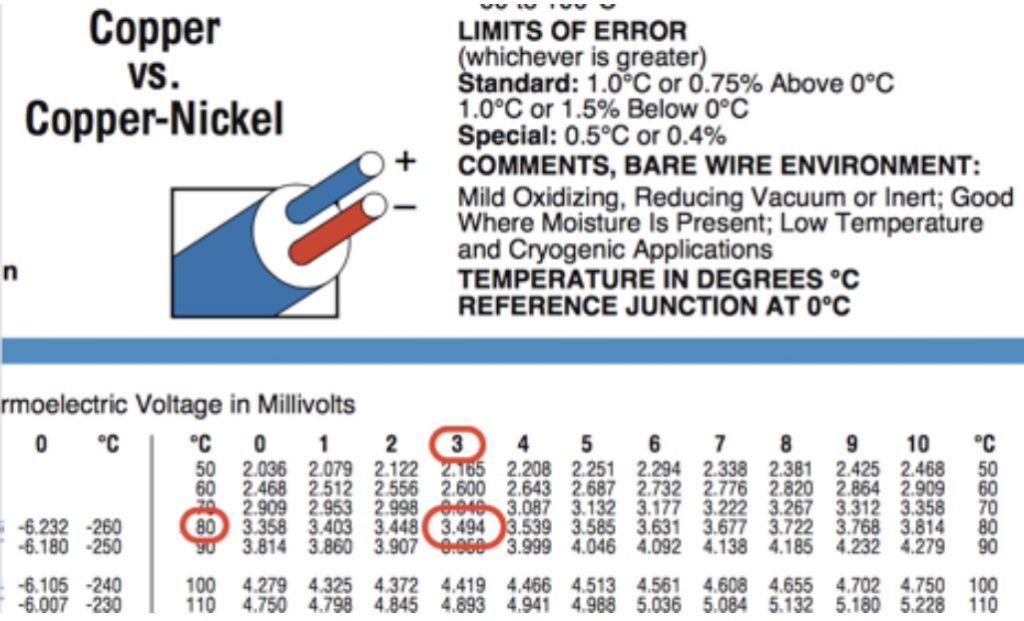
This image of a reference table is grabbed from the OMEGA page for type T thermocouples. The process is exactly the same for other types of thermocouples, including Type K. Just make sure you use the right table for your thermocouple type. There’s lots more information and similar tables for different types of thermocouples.
The potential across a type T junction at 83 C would be 3.494 mV, referenced to another junction at 0 C. Check yourself by reading the value for a junction at 99 C. You should get a value that’s 0.785 mV higher than the 3.494 mV we got for 83 C.
If one junction was at 83 C and the other junction was at 99 C the measured voltage for the combination would be 0.785 mV, a very small voltage to measure accurately, especially in an electrically noisy environment.
The more usual case would be a reference junction close to room temperature, say 20 C. What would the potential be for the reference junction?
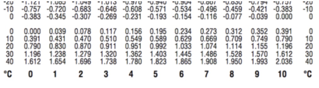
I get 0.790 mV at 20 C. If I plug a thermocouple into a voltmeter that’s at 20 C and have the thermocouple bead at 20 C, then both with have a junction potential of 0.790 mV in opposite directions and they will cancel out. The meter will read zero volts.
If the measurement junction is at 83 C and the meter still at 20 C, then the reading will be 3.494 – 0.790 = 2.704 mV, although we would like to work it the other way around. If the meter was at 20 C and read 3.235 mV, what would the temperature of the bead have to be?
3.235 + 0.790 = 4.025 mV. From the table we get 3.999 for 94 C and 4.046 for 95 C, so interpolating should give us about 94.5 C.
What if the meter wasn’t at 20 C? We would just use the potential for whatever temperature the meter was at. That means we need to know the temperature of the meter to interpret the voltage result by doing Cold Junction Compensation.
If the meter read 3.931 mV and was in cold room at 12 C, what would be the temperature of the measurement junction?
3.931 + 0.470 = 4.401 mV, which is about 102.6 C from the table. This kind of math is tedious to do by hand with table lookups, but easy to do with a computer.
There’s some useful background information in the Wikipedia article on thermocouples, but for authoritative information you should go to a major manufacturer like OMEGA or a standards body like ASTM or NIST.
Thermistors
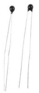
Thermistors are inexpensive temperature sensors for moderate temperatures, and their resistance varies non-linearly. Some simple, inexpensive thermistors I bought on eBay provided only the specs below and a datasheet. All thermistors have two leads and their resistance varies depending on their temperature. They are usually characterized by their resistance  at
at  and a constant B that defines the shape of the curve.
(1) 
Note that the temperatures for the equation are in degrees Kelvin, even though most of the specifications are for temperatures in Celcius. The simplest way to measure the resistance is using a voltage divider.
Sample Manufacturer’s Data Sheet: https://www.taydaelectronics.com/datasheets/A-409.pdf
100 x 10K OHM NTC Thermistor 5mm – $8.99 US – Free Shipping
Manufacturer: THINKING, RoHS: Yes
Specification: B Constant 4050K, Resistance 10K OHM, Temperature -30°C to +125°C
Thermistor Type: NTC Thermistor, Tolerance ±5%
Adafruit provides very useful practical application information for getting started (Note that they assume an UNO with 10 bit ADC, 1023 max reading, and 5V scale). This code from RWS-Notes shows how to convert thermistor analog input readings to temperature values.
MECH 217 2021 thermistors with a green bead were 10K at 25C with B=4050
MECH 217 2021 thermistors with a black bead were 10K at 25C with B=3435
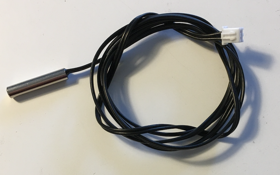
MECH 217 2021 and onward: thermistors with a stainless steel shell are 10K at 25C with B=3950
MECH 217 2022 and onward: thermistors with a black bead are 10K at 25C with B=3950
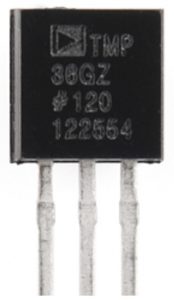
Analog Devices TMP 36 Temperature Sensors
Manufacturer’s Data Sheet: http://www.analog.com/media/en/technical-documentation/data-sheets/TMP35_36_37.pdf (This one pops up close to the top of the list if you just Google TMP36.)
Adafruit Product Page: https://www.adafruit.com/product/165
Adafruit Tutorial Page: https://learn.adafruit.com/tmp36-temperature-sensor
The TMP36 is one of a family of analog temperature sensors from Analog Devices. The TMP35/36/37 differ by scale factor and offset. The LM35 from Texas Instruments provides similar capabilities.
The low voltage output is great for 3.3V micro-controllers, but the resolution may be limited on the 5V analog range of an Arduino Uno.
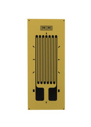
Student Strain Gauges
Manufacturer’s Product Page: https://micro-measurements.com/educators
These student strain gauges have a nominal resistance of 120 ohms and a gauge factor of about 2.09 and are an economical choice for use in our labs.
The cantilever beam load cell below is composed of 4 strain gauges mounted on a 1/2 inch aluminum square bar. You can clamp it to your bench and hang a bucket from the end to carry the load. (video 2:21)
Cadmium Sulphide Photocells
Example Supplier Page: https://www.digikey.ca/en/product-highlight/a/advanced-photonix/cds-photocells
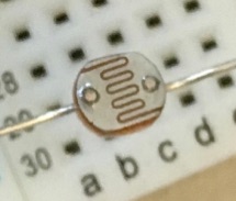
CdS photocells act as a resistor with a variable value. The more light falling on the photocell, the lower the resistance. They can be wired with a constant resistor in a voltage divider to provide an illumination dependent voltage output. The magnitude of the resistance depends on manufacture and is not usually marked directly on the sensor. You can expect to encounter resistances in room light ranging at least from 500 Ohms to 100000 Ohms and will need to choose an appropriate resistor value for the other side of the voltage divider depending on your application.
Calibration to produce an actual illumination measurement in engineering units will be much more complex than simply detecting the difference between bright and dim lighting.
Analog Devices ADXL335 Accelerometer
Sparkfun’s Product Page: https://www.sparkfun.com/products/9269
Manufacturer’s Datasheet: https://www.sparkfun.com/datasheets/Components/SMD/adxl335.pdf
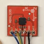
The ADXL 335 Accelerometer works by measuring the forces necessary to accelerate a small mass inside the chip, essentially like a tiny load cell. (Check the data sheet and the web for a little more detail of the internals if you are interested.) The mass inside the chip moves with the chip, so measuring those forces gives a combination of both gravity and any acceleration of the chip. The chip is the black component in the middle of this breakout board from Sparkfun. The have included 0.1 uF capacitors on each analog channel to limit the bandwidth of the output to 50Hz, so sampling the output at 100Hz should capture all the information available.
There is no on-board regulation, so the provided power must be between 1.8 and 3.6VDC. Use the 3.3 V supply when connecting to an Arduino UNO!
If you apply a higher voltage, you may get noisy, hard to integrate acceleration data, and you may damage the chip. The ADXL voltage outputs vary from chip to chip, so you need to calibrate to find the scale and offset to make a conversion. To calibrate an analog accelerometer you can hold it still, align the axis you are interested in with the vertical and measure 1 g output.
ST Microelectronics LIS3DH Digital Accelerometer
Manufacturer’s Data Sheet: https://www.st.com/resource/en/datasheet/cd00274221.pdf
Adafruit Product Page: https://www.adafruit.com/product/2809
Adafruit Tutorial Page: https://learn.adafruit.com/adafruit-lis3dh-triple-axis-accelerometer-breakout
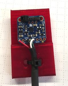
The Adafruit Breakout board makes it easy to connect this digital accelerometer using I2C. Connect SCL (green in this photo) to pin A5 on an Arduino UNO and SDA (white in this photo) to pin A4 and run the example code for the Adafruit LIS3DH/acceldemo to understand how it works.
You will need to install the Adafruit LIS3DH library following a process similar to the one used for the BMP180 or BME280.
Media Attributions
- BME/BMP Breakouts © Rick Sellens is licensed under a CC BY (Attribution) license
- Sensor BMP180 © Rick Sellens is licensed under a CC BY-SA (Attribution ShareAlike) license
- Sensor BME280
- Sensor PX137 X3 © Rick Sellens is licensed under a CC BY-SA (Attribution ShareAlike) license
- Sensor PX137 Mounted © Rick Sellens is licensed under a CC BY-SA (Attribution ShareAlike) license
- Sensor Type K TC © Rick Sellens is licensed under a CC BY-SA (Attribution ShareAlike) license
- Sensor Type T Table 1 © OMEGA adapted by Rick Sellens is licensed under a All Rights Reserved license
- Sensor Type T Table 2
- Sensor Thermistor
- SS Thermistor 2020-10-05
- Sensor TMP36 © Rick Sellens is licensed under a CC BY-SA (Attribution ShareAlike) license
- Sensor Strain Gauge © Micro Measurements is licensed under a All Rights Reserved license
- Sensor CdS © Rick Sellens is licensed under a CC BY-SA (Attribution ShareAlike) license
- Sensor ADXL335 © Rick Sellens is licensed under a CC BY-SA (Attribution ShareAlike) license
- Sensor LIS3DH © Rick Sellens is licensed under a CC BY-SA (Attribution ShareAlike) license
