9 Your Microcontroller
The 2021 – 2023 Kit Editions
For Fall 2021 we packaged a simple version for students to complete some self contained activities at home to prepare for labs involving additional components and equipment provided on campus. The 2022 and 2023 kit is identical, except the potentiometer has been deleted.
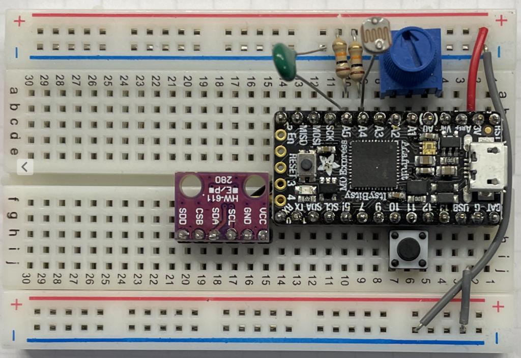
You may need to make the connections yourself, while the photo shows them already made, with the Itsy Bitsy located on the right:
- The G pin is connected to the bottom blue rail for ground, and the two blue rails are connected together. (The grey wire is tucked under the USB connector to keep it from catching on things.
- The 3V pin is connected to the top red rail to provide 3.3 volt power from the regulator on the Itsy Bitsy. You may want to add a connection between the two red rails to have power on both sides of the board.
- A 10K potentiometer is plugged into pins A0, A1, A2 for the 2021 edition. In 2022 you will use a better potentiometer in the with angle indicator, supplied in the lab.
- The pushbutton below the Itsy Bitsy is connected between pin 10 and pin 12, so pin 12 will be grounded when the button is pushed. (Provided pin 10 is set to ground in your code with
pinMode(10,OUTPUT); digitalWrite(10,0);) - Nominally 10K resistors are connected between +3.3 and both pins A4 and A5. Pin A5 is then connected to ground through a nominally 10K thermistor to form a voltage divider so the measured voltage on A5 will depend on the resistance of the thermistor, which will change with temperature. A similar connection of a CdS photocell from A4 to ground will let you measure the light level. Do not lose any of these small components!
- A BMP280 pressure transducer breakout board (purple) is mounted, waiting for you to make the I2C measurement connections with jumper wires.
- We will take advantage of the LED and current limiting resistor already attached to pin 13 on the microcontroller board for an output indicator.
About Microcontrollers and Arduinos
Arduino is a trademark for a maker of microcontrollers and they have made their UNO R3 reference design available as Open Source Hardware for anybody to use and to market under their own names. There are a wide variety of microcontrollers that can be programmed using the Arduino IDE. Here are some examples (video 8:03):
The key features of a microcontroller are:
- Stand alone processor for programmable control
- Real world inputs and outputs
- Analog voltages, e.g. 0 to 3.3 volts continuous
- Digital signals, off/on, 0/1, 0/3.3 volts
- Communications ports like Serial, I2C, SPI, etc.
Arduino UNO R3
The classic Arduino is the UNO R3, or a clone following the open hardware R3 reference design like the Metro 328, and using the 8 bit Atmel 328 processor. MECH 217 used the UNO up to Fall 2019 and there are enormous numbers of tutorials and other reference materials for UNO based learning and projects. Understanding the UNO is a good start for moving up to more advanced microcontroller boards, and for following the resources in this book and other locations.
Adafruit Itsy Bitsy M0 Express
This very small board has been provided to all MECH 217 students for the Fall 2020 and later offerings and there are a few key differences to be aware of. Almost all of them are improvements. The product tutorial page covers them in much more detail! (If you are ever having difficulty, double click the reset button and the LED near the USB should turn green, indicating the board is ready to receive a program from the IDE.)
3.3 V Power and Logic: Almost all of the voltage levels on the Itsy Bitsy are 3.3 volts maximum. Be careful not to connect 5 volt signals or you could damage your board! Avoid the pins labelled 5!, Bat, USB, and VHI. Newer sensors run on 3.3V power.
General Purpose Input Output (GPIO) Pins: While the UNO had fourteen pins numbered 0 to 13, there are fewer available on the sides of the Itsy Bitsy, 0-2, 7, and 9-13. This is still plenty of digital level pins for connecting buttons and LEDs.
Analog Input Pins A0-A5: The range on the Itsy Bitsy defaults to 3.3 volts instead of 5 and adds 3 internal voltage references at 1.0, 1.65, and 2.23 volts. This largely eliminates the need to use an external reference voltage to extend the UNO’s single 1.1 volt internal reference. The Itsy Bitsy also provides higher resolution ADC for better accuracy! A0 can also be used for true analog output.
Serial Communication: The Itsy Bitsy communicates over the USB on port name Serial and with pins 0 and 1 using a separate port name Serial1. This lets you keep on communicating with your computer for debugging while talking to another device like a GPS on Serial1. The UNO provided only a single port labelled Serial for both the USB connection and the RX/TX functions on pins 1 and 0. The Itsy Bitsy also appears to negotiate high speed communications on the USB, so it doesn’t matter what speed you set in Serial.begin()as long as you set something.
I2C Communication: The Itsy Bitsy provides separate pins labelled SDA and SCL for communicating with sensors, while the UNO required A4 and A5 to make those connections.
32 Bit Processor at 48 MHz is much faster than the 8 bit UNO at 16 MHz, and supports 32 bit integer types by default, eliminating problems experienced between unsigned and unsigned long on the UNO. It also tracks time fairly accurately to the microsecond with both micros() and millis() functions.
Serial.printf("%8.2f",x) works for formatted floating point output, provided you #include “RTClib.h”. This eliminates a lot of tedious Serial.print(x) of just one thing at a time.
Circuit Python: You can program the Itsy Bitsy Express in Python, however it is not as fast as C, and won’t be used in MECH 217. The CIRCUITPY USB device will be overwritten with your first successful Arduino upload, and you will start seeing the ITSYBOOT USB device as a drive attached to your system.
Arduino IDE Setup: You need to add https://adafruit.github.io/arduino-board-index/package_adafruit_index.json to the Additional Boards Manager URLs: in Arduino IDE Preferences. Then you need to install Arduino SAMD Boards and Adafruit SAMD Boards using Tools/Board/Boards Manager, and RTClib by Adafruit using Tools/Manage Libraries… from the Arduino IDE menu. (More Setup Details)
The 2020 COVID-19 Edition (Obsolete)
For Fall 2020 we packaged a specially assembled version for students to help avoid connection mistakes that could be hard to diagnose remotely.
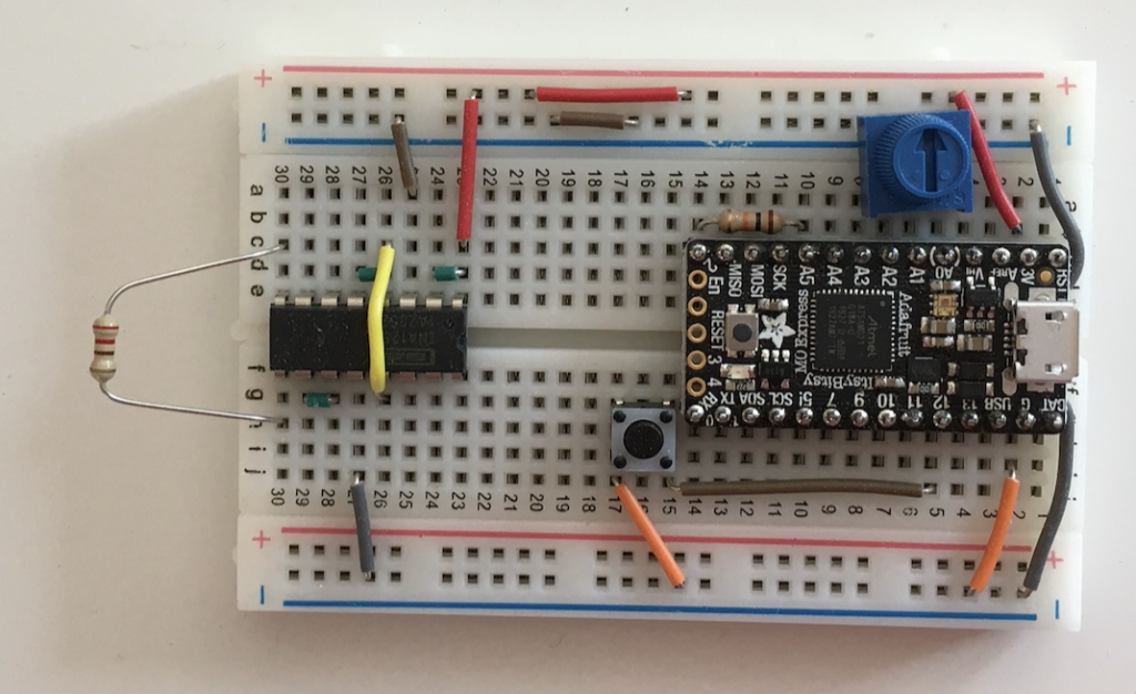
The Itsy Bitsy is located on the right, with the following connections already made:
- The 3V pin is connected to the top red rail to provide 3.3 volt power from the regulator on the Itsy Bitsy. There’s extra jumpers pushed into the red and blue rails to use later with an I2C breakout board. (Check your kit notes for the actual measured regulator voltage.)
- The G pin is connected to the bottom blue rail for ground, and the two blue rails are connected together. (The grey wire is tucked under the USB connector to keep it from catching on things.
- A 10K potentiometer is plugged into pins A0, A1, A2.
- The pushbutton to the lower left of the Itsy Bitsy is connected between ground and pin 12, so pin 12 will be grounded when the button is pushed.
- A nominally 10K resistor is connected between pin 2 and pin A5. (Check your kit notes for the actual resistance we measured before we installed it. Do not remove this resistor!)
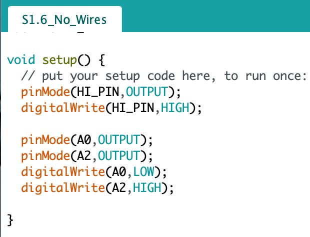
In order to make this all work, we need to set the output voltages on some of the pins. This setup code makes pin 2 an output pin and sets the voltage HIGH (3.3 volts) so it can drive the voltage divider used in the multimeter sketch from pin A5.
Likewise, it makes pins A0 and A2 outputs at LOW (0 volts) and HIGH (3.3 volts) respectively. They supply power to the potentiometer, so that the middle pin voltage (attached to pin A1) can be varied between 0 and 3.3 volts by turning the potentiometer knob.
At the left of the board we have installed an INA 125 Instrumentation Amplifier for reading small transducer signals like thermocouple voltages. Please don’t remove it as the pins are easily bent and broken! Starting from the upper right at pin 1 of the INA 125, row 23 of the breadboard where the red wire connects:
- Pins 1 and 2 are connected to +3.3V and pin 3 is connected to ground. These connections provide operating power.
- Pins 4 and 5 are connected together, and across the chip to pin 13 with a yellow wire. This sets the pseudoground reference voltage of the amplifier to 1.24 volts.
- Pins 6 and 7 are left open for the small signal differential input voltage.
- Pins 8 and 9 are connected by a resistor that sets the gain of the amplifier. You will need to switch out this resistor to get different gain values.
- Pins 10 and 11 are connected together and provide the amplified signal output.
- Pin 12 is connected to ground for reference.
The space in the middle leaves room for some other circuit elements that we will include for different labs, particularly some I2C breakout boards you will need to connect yourself. The kits also includes a USB cable, some jumper wires, a photocell, and an assortment of colour coded resistors including:
- 3 pieces 10K Ohm resistors useful for pull-up, pull-down, or providing a small load on inputs or outputs to complete the circuit and allow current to flow.
- Gain resistors, e.g. 68, 150, 220, 330, 500, 1000 Ohms or similar so you can set the gain on your amplifier to match the requirements for different measurements.
We have tested your breadboard before sending it out to you. Your kit will include a label on the back of your breadboard similar to:
Kit Calibration Numbers
Regulator Voltage ___________ (nominally 3.3 VDC)
10K resistor actually ___________ Ohms (installed between pins 2 and A5)
with the measured values for your particular hardware. We have also applied a small signal to the amplifier to confirm the circuit is functioning as it should be. (Using a resistor string of 10000-10-10000 resistors in series as a voltage divider allows us to apply voltages of about 1.65 volts to both pins 6 and 7, with a difference of about 10/20000 = 0.5 mV between the two pins.)
Kit Type 1 is compact for easy mailing to remote locations and also includes:
- A waterproof thermistor on leads with female connectors that you can connect to the breadboard using jumper wires.
- A bare wire thermocouple with male pin connectors for the breadboard
- A BMP280 or BME280 pressure sensor breakout board
Kit Type 2 will be supplemented with materials to be picked up at Queen’s during the term for load cell measurements and also includes:
- A BMP280 or BME280 pressure sensor breakout board
Kit Type 3 also includes:
- A BMP280 or BME280 pressure sensor breakout board
- An LIS3DH Accelerometer breakout board
Media Attributions
- ItsyBitsy2021Kit © Rick Sellens is licensed under a CC0 (Creative Commons Zero) license
- 2020 COVID Kit © Rick Sellens is licensed under a CC BY (Attribution) license
- Screen Shot 2020-09-15 at 08.17.25 © Rick Sellens is licensed under a CC0 (Creative Commons Zero) license
