33 Components
This chapter provides some background on selected electronic and mechanical components, where to find them, and how to use them.
Potentiometers
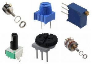
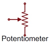
A potentiometer consists of a fixed resistor and a wiper that can make an electrical connection anywhere along the physical length of the resistor. If the two outside pins from either end of the fixed resistance are connected to a positive voltage and ground, the centre pin will vary over the voltage range as the potentiometer shaft is rotated. See the segment on voltage divider circuits.
If the centre pin and one of the outside pins are connected in a circuit, then the resistance will vary between 0 and the full resistance as the shaft is rotated. This could result in a short circuit if the pot directly connects +5 and ground. Use an additional resistor to limit the current and avoid destroying the potentiometer.
Servomotor with Analog Feedback
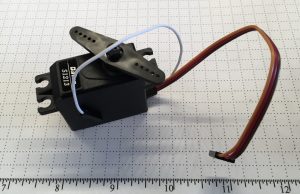
Servomotors move to an angular position in response to control pulses as detailed in this general tutorial. Typically a 5 volt power supply is used, and some servo motors will run on higher voltages for more torque. Most servos will also run on a 3.3 volt supply, but will run more slowly and not develop as much torque.
Follow the link for product details or check this product specific tutorial. These servos provide analog output as an indication of their current angular position. The red and brown wires provide power and ground, the orange wire provides the PWM signal, and the white wire is the potentiometer output.
INA 125 Instrumentation Amplifier
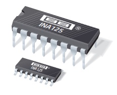
The INA125 amplifies small differential voltage signals to make them large enough to read with an Arduino ADC. It provides several key advantages for this course, including a reference voltage for pseudoground use with single sided power supplies, and being available in a dual inline package (DIP) format that fits in the breadboards.
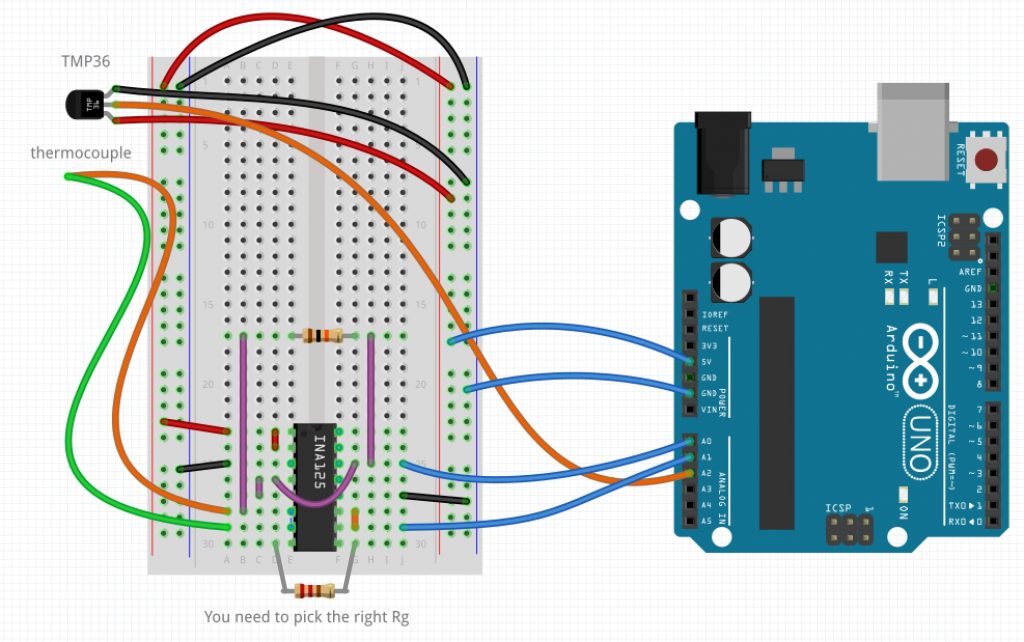
Pay particular attention to figure 3 on page 11 for connecting thermocouples with a bias current return path, figure 6 on page 13 for a 2.5 volt pseudoground configuration, and to “INPUT COMMON-MODE VOLTAGE vs OUTPUT VOLTAGE, VS = ±5V” on page 5 to understand the limits on input and output voltage capabilities.
Follow along as we wire up the amplifier to provide load cell input to an Arduino UNO. (video 10:52)
Wiring an INA125 for a Full Bridge Load Cell
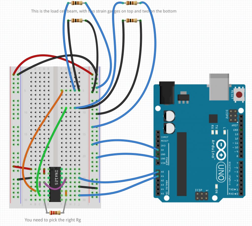
Counterclockwise from Pin 1 at the top left on the INA125 chip:
- Connect pins 1 and 2 to +5V
- Connect pin 3 to ground
- Connect pins 4 and 5 to each other and to pin 14 (2.5V pseudoground) or to pin 13 (1.24V pseudoground)
- Connect pins 6 and 7 to the low voltage input
- Connect pins 8 and 9 connected with a gain resistor. The resistance determines the gain.
- Connect pins 10 and 11 to each other and to the Arduino. This is the output voltage to be measured.
- Connect pin 12 to ground
- Connect pin 13 or 14 to pins 4 & 5 and to the Arduino to keep track of the pseudoground voltage.
If you have problems, be sure to go around the chip pin by pin to make sure they are connected properly and check that you get the voltages you expect. If the output is about 0.10V or 4.2V and doesn’t change with the input, you have probably set the gain too high, or reversed the polarity of your inputs. If your output is noisy, you may want to add a load resistor (~10K) between the output (pins 10 and 11) and your pseudoground (pin 13 or 14) to allow a small current to flow from the output of the amplifier.
Wiring an INA125 for Thermocouples Require a Resistor
Media Attributions
- VariousPotentiometers
- PotentiometerSymbol
- Servo with Analog Output © Rick Sellens is licensed under a CC BY (Attribution) license
- INA125Chip © Texas Instruments adapted by Rick Sellens
- Load Cell.fzz © Rick Sellens is licensed under a CC0 (Creative Commons Zero) license
- Thermocouple and TMP36.fzz © Rick Sellens is licensed under a CC0 (Creative Commons Zero) license
