50 Instrument Networks
Sailing instrumentation is much more useful if the output from multiple measurements can be shared and combined to record and display the results using some sort of communications network. The National Marine Equipment Association (NMEA) defines proprietary network standards that are widely used in the industry. NMEA-2000 is a high speed network that is electrically compatible with the Controller Area Network (CAN) bus, standard in the automotive industry, but using different messages specifically for marine applications. NMEA-183 is an older, slower standard, electrically compatible with RS-232 serial communications and more easily interfaced to microcontroller serial ports. Although proprietary, there are many public sources describing NMEA-183 messages. As a dominant manufacturer, RayMarine uses proprietary connection hardware and similar standards in their SeaTalk (NMEA-183) and SeaTalkng (NMEA-2000) interconnection systems.
CAN Bus
 CAN bus is the international automotive communications standard built into all cars since 1996. It allows bi-directional communications among multiple devices over a single cable. Fusion is a small independent company that makes a CAN bus adapter for Teensy 3.5/3.6 boards. https://www.tindie.com/products/fusion/single-can-bus-adapter-for-teensy-35-36/
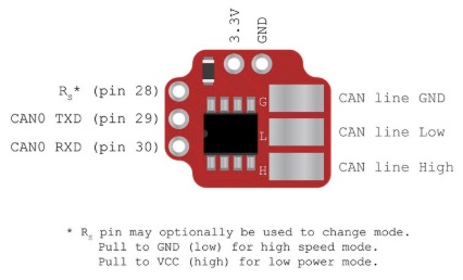
“This tiny backpack includes one SN65HVD230D transceiver for connecting to virtually any CAN network. Includes 120Ohm termination resistor. The unobtrusive design allows you to easily access surrounding pins if needed.
An extra Rs pin for provides switching to high speed mode (strong pull down to GND) or low power mode (strong pull up to VCC). The board can also be used on Teensy 3.1/3.2 on pins 2,3,4 instead of 28,29,30 (see pinout), but short wires will need to be lead to 3.3V/GND pins. It can be breadboarded too.
The recommended library for this board is the FlexCan lib included with Teensyduino installation.”
NMEA-2000 and SeaTalk ng
These fast communications networks based on CAN bus are the mature standard for modern marine systems. They are beyond the scope of simple microcontroller projects, and inserting our own hardware into the network could compromise the functioning of instruments required for safety. A commercial adapter like the Actisense NGW-1 can pull out the signals we would like to use as NMEA-183 sentences, while isolating the main network from our experimenting.
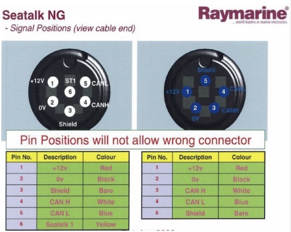
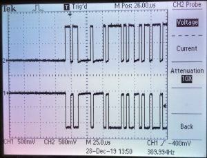
N.B. Spur cables to SeaTalk1 carry only red, yellow, and shield conductors and are thinner than regular spur cables. When plugged into a standard T connector, there is no signal on the yellow ST1 conductor for either the ST1 cable or the STng cable. On the STng cable the red conductor is at 12 volts relative to the black ground cable. The blue and white conductors both average about 2.5 volts from ground. The white CAN H conductor shows pulses on the scope going about 1 volt higher, minimum pulse length about 4 microseconds or 250 kHz. The blue CAN L conductor shows similar pulses going about 1 volt lower.
A brief attempt to read them on a Teensy 3.5 with the FlexCAN library did not succeed – may just need more work.
NMEA-183
NMEA-183 provides two way serial data, usually conforming to RS-232 standards, usually at 4800 baud, often electrically isolated from the sending/receiving equipment. If unsure about a particular piece of equipment, check the characteristics of the output signals on an oscilloscope, as there is significant variation. The RS-232 voltage levels are higher than typical microcontroller voltages of 3.3 or 5 volts and the MAX3232 chip provides an easy way to manage conversion of voltage levels, using charge-pumping to produce the higher voltages from a low voltage supply.
Although superseded by NMEA-2000 for all but the simplest network topologies, there are enough legacy systems in operation to ensure that NMEA-183 remains relevant. NMEA-183 is also used as the basis for communications by many GPS modules that can be incorporated directly into microcontroller systems with serial communications at 3.3 or 5 volts.
NMEA-183 Sentences
Each NMEA communication comes in a sentence like $IIMDA,,I,,B,,C,21.8,C,,,,C,,T,,M,,N,,M0F. The $ identifies the start of a sentence, which ends with a new line. The first two letters after the $ identify the source (Integrated Instrumentation in this case) and the remainder define the sentence format (MDA for Meteorological Composite in this case). The following fields are separated by commas and depend on the defined format of the sentence. Field values can be left out as long as the commas are present. This sentence leaves out a lot, telling us little besides the water temperature of 21.8C. The two characters following the asterisk are a checksum to allow validation of the sentence. Publicly available format information can be found at http://fort21.ru/download/NMEAdescription.pdf among other sources. The Adafruit GPS Library for the Arduino IDE provides examples of reading and parsing NMEA sentences coming in from a GPS module and the same approach can be used for other types of instruments.
Talkers, Listeners, and Multiplexing
Although NMEA-183 devices are capable of bi directional communication, many configurations consisted of a single “talker” (an integrated instrument controller) that would send the same signal to multiple “listeners” (displays in multiple locations). The listeners would usually be passive, not sending any information back to the talker, and could share the same electrical conductor provided attention was given to circuit compatibility. The receiving line (RX) of a listener can only be connected to the transmitting line (TX) of a single talker. An adequate network can often be cobbled together by connecting the RX and TX lines to different devices, e.g. having a chart plotter talk to a VHF radio to provide position data, while listening to an instrument system to display depth and wind data, but it rapidly becomes complicated and difficult to extend for future expansion.
The inability to share cabling for multiple talkers requires a star topology. Multiplexing can take the TX from one talker and repeat it over outputs to the RX of multiple listeners and also take the TX from those multiple listeners, queue the sentences, and repeat them to the RX of the primary talker. Alternately, it could mean repeating every sentence from every device back out to every other device, which could quickly overwhelm the typical 4800 baud connection of NMEA-183. A custom microcontroller based switch can solve this problem by providing smart, programmable sharing of data among legacy devices, and provides an interesting project, although the best way to manage legacy hardware is probably to provide a single NMEA-2000 to NMEA-183 adapter for each connection.
Signature Solution
Upgrading instrumentation on Signature provides a special case, with multiple NMEA devices, a 1984 vintage Ockam racing instrument computer, CAN bus instrumented electric propulsion system, and the need to extract and inject data feeds for our experimental efforts. A Teensy 3.5 with USB plus 5 additional serial ports provides a base for custom multiplexing of bi-directional signals among devices:
- Serial provides the USB communication with the programming PC and console.
- Serial1 provides bidirectional communication with a SeaTalkng network via an Actisense NGW-1.
- Serial2 provides bidirectional communication with a chartplotter or other GPS source, initially an older Standard Horizon CP150C.
- Serial3 listens to the Standard Horizon Matrix VHF that reports AIS data.
- Serial4 provides bidirectional communication with the Ockam racing instruments computer.
- Serial5 provides bidirectional communication with another microcontroller to manage wireless communications.
In February 2020 Signature/CustomMux was running on the Teensy 3.5 to collect test data on the home test bench. It was an updated version of NMEA_Multi, taking advantage of the incorporation of a lot of RWS_NMEA code into the adafruit GPS library. An ESP32 Feather mounted on the same large perma-proto board provided wifi and listened to the output from Serial5 on the Teensy 3.5
Actisense NGW-1 Configuration
The standard version of the NGW-1 ships with a 4800 baud speed on the serial side and connects to STng through an adapter cable. 4800 baud worked fine, but is not fast enough to carry the AIS sentences produced by the Matrix VHF at 38400 baud. Raising the baud rate and other configurations requires custom Windows software from Actisense.
- Install and run the latest Acti-Patch app to upgrade the firmware. (mine went from v2.420 up to 2.660)
- Install and run the Actisense Toolkit. Create a base configuration using the AIS38400 template, then increase the speed to 115200 and send it to the NGW-1.
- The NMEA Reader app has an “unhandled comms error that is a small bug with NMEA Reader, but it can be overcome by closing the COM Port, selecting the baud rate required, then closing the program. Once the program is re-opened, set the baud rate first, then open the COM Port and it should resolve the error. We are looking to find out what is causing this error, it points towards a registry key error as I can only replicate it the first time NMEA Reader is installed and run as I can recreate it by deleting my registry key entry for NMEA Reader and then loading the program again.” – Josh Keets, Actisense
Media Attributions
- Fusion Single CAN Adapter adapted by Rick Sellens is licensed under a All Rights Reserved license
- STng Pins adapted by Rick Sellens is licensed under a All Rights Reserved license
- STng CAN Signals
