28 Tools and Basic Circuits
We will use Ohm’s Law to understand some very basic resistive circuits in making measurements. Our primary tools in assembling and testing those circuits will be a multimeter for steady state and an oscilloscope to see transients. We will rely on a little knowledge of RC Circuit Transients and familiarity with Voltage (V), Current (I), Resistance (R), and how they are related by Ohm’s Law:
(1) 
Breadboards
To hold our circuits together and make electrical connections we will use solderless breadboards. This video (5:32) from Adafruit shows how they work and a little about moving on to more reliable soldered circuits.
Multimeter
Your multimeter is the most important diagnostic tool and every engineer should own one. A cheap but useful meter can be found for under CDN$10 on eBay!
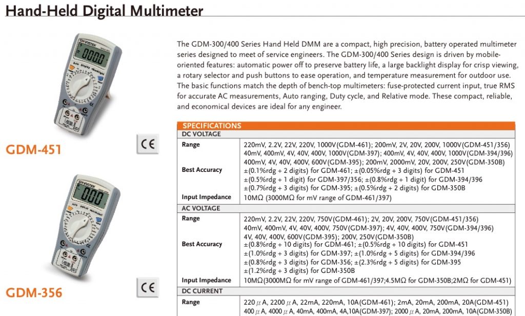
You will see lots of different multimeters with different functions and accuracies, but they all have similarities. We will concentrate on three functions: DC voltage, resistance and continuity. For most accurate results, use the best meter available and always use the lowest scale that will still give you a reading. (video 4:38) The 4-1/2 digit multimeters with the yellow or green bodies are the most accurate meters we have in the MECH 217 labs and may be treated as reference quality instruments for your work.
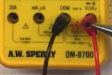
Insert the Black Lead into the common terminal, usually marked COM. Insert the red lead into the terminal for the type of measurement you want to make. Usually the resistance, voltage, and continuity scales all use the same connection. Although there is no electrical difference between the two lead wires, there is a strong convention for these colours, and you may confuse us if you don’t follow it.
Resistance Measurements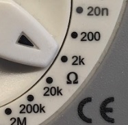
For resistance measurements select the smallest Ohm range that will still allow you to measure. The Omega symbol is usually used to mark the resistance measurements and this photo shows a selection of the 2 kOhm or 2000 Ohm range. We would use this range to measure resistances between 200 and 2000 Ohms.
Touch the leads to opposite sides of the resistance you want to measure. To measure individual components like resistors, they must be disconnected from the rest of the circuit. Otherwise the meter will measure the combined resistance of all the connected components.
DC Voltage Measurements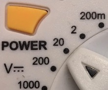
For DC voltage measurements select the smallest DC Volts range the will still allow you to measure. The V, with the line and dashed line is usually used to represent DC voltage (a little sine wave is used for AC). This photo shows the 20 volt DC range selected. We would use this range for measuring DC voltages between 2 and 20 volts, including the voltages in the 0 to 5 volt operating range of circuits with the Arduino UNO.
Touch the leads to two separate locations in a circuit to measure the voltage difference between them. Red is positive and if you reverse the leads you will see a minus sign in the display. It is often useful to plug the black lead into ground (zero volts) and just move the red lead around. The exception is when you really want a measure of differences, like on the input to an amplifier.
Continuity Testing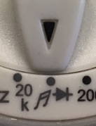
For continuity testing, we select the continuity range, usually marked with the diode symbol (arrow with a bar on the point) or a musical note to indicate it makes a tone. When the resistance between the leads is very small, the meter will make an audible signal and display a low resistance value on the screen. This function is most useful for testing when two points in the circuit are actually wired together to make an electrical connection. It can help you determine the internal connections in switches such as pushbuttons and detect bad or missing connections in your circuits.
Touch the leads to the two points as with a resistance measurement, and remember the meter will indicate continuity if there is any low resistance connection between the two points.
Practical Examples You Might Encounter

Multimeters 101 is another eCampus Ontario Pressbook that provides a much more in-depth look at how to use a multimeter.
Colour Digital Oscilloscope
Using the oscilloscope you can see time series plots of signals on the screen in real time. This is really good for looking at how things are changing for diagnosing problems, or for seeing the noise on what you thought was a DC signal. (video 7:41)
We use oscilloscopes whenever we want to see changes that are too fast to follow on a multimeter, including the PWM signals that result from the analogWrite() function of the Arduino and the rapidly changing electrical noise on our power supplies and analog sensor outputs. We will usually want to follow these steps:
- Use the channel menu to set AC coupling, so you only see the time varying part of the signal.
- Set the probe switch to x1 on the end of the cable, and set the menu to use the probe on x1.
- Use the measure button to select, mean, RMS, and peak to peak display on your screen.
- Connect to alligator clip to ground and the probe tip to the signal you want to measure.
- Adjust the voltage on the Y axis with the vertical scale knob for the channel, and the position knob.
- Adjust the time on the X axis with the horizontal scale knob.
- Adjust the trigger if needed to isolate features of interest. Be sure the Run/Stop button is green.
Other ‘scopes may have different controls, but they all have similar features modelled after the interface of traditional analog oscilloscopes.
Indicators and Controls
LED Indicators
Light Emitting Diodes (LEDS) can be used in series with a current limiting resistor to provide a digital voltage indication. In 5 volt circuits a 1K resistor will restrict current to a maximum of less than 5 mV, which will usually prevent damage to an LED. Choose more carefully if you want to get the most light possible from your LED without frying it. (video 3:53)
Pushbuttons with Pull-Up or Pull-Down Resistors
Using a pull-up resistor will make sure pin 7 is at 5 volts unless the button is pushed, pulling the voltage down to ground. You could also do the same thing in reverse, swapping the positions of the pushbutton and resistor to pull pin 7 down to ground. On some microcontrollers you can use their internal pull-up resistors and make the circuit simpler. The higher the pull-up resistance, the less current will flow, so a 10K resistor would result in a half a milliamp of current flowing in this example. (video 4:58)
Variable Resistance Circuits
Many sensors respond by changing resistance in response to changes in the measurement quantity. RTDs and thermistors change resistance with temperature, while strain gauges change resistance when they are deformed.
Voltage Dividers
Two resistances in series split, or divide the supply voltage between them in proportion to the size of the resistance. Ohm’s Law makes it straightforward to calculate the intermediate voltage. These circuits let us measure changes in resistance using microcontroller analog to digital converters (ADC) that are sensitive to analog voltage. (video 5:59)
Voltage dividers let you produce a voltage signal anywhere between 0 volts and the supply voltage by allowing current flow through resistors in series. A voltage can be split by 2 fixed resistors (video 3:41)
An adjustable voltage signal can be created with a potentiometer providing a voltage divider with two continuously variable resistors. (video 3:43)
Media Attributions
- Tools Multi 1 © Rick Sellens is licensed under a CC0 (Creative Commons Zero) license
- Tools Multi 2 © Rick Sellens is licensed under a CC0 (Creative Commons Zero) license
- Tools Multi 3 © Rick Sellens is licensed under a CC0 (Creative Commons Zero) license
- Tools Multi 4 © Rick Sellens is licensed under a CC0 (Creative Commons Zero) license
- Tools Multi 5 © Sperry Instruments is licensed under a All Rights Reserved license
- Tools Multi 6 © GW Instek is licensed under a All Rights Reserved license
