25 ATP Synthase
The energy stored in the proton gradient can be used in multiple ways, such as powering the rotation of the bacterial flagellum (Stryer Fig. 34.28), but the most important case is the powering of ATP synthesis in the mitochondrion (and the chloroplast, too; we won’t discuss the chloroplast case here, but it is similar to that of the mitochondrion.)
ATP synthesis takes place in another protein complex of the inner mitochondrial membrane. Sometimes it is called “Complex V”, but we will call it the ATP synthase complex. This enzyme was discovered as a catalyst of the hydrolysis of ATP to ADP and Pi, i.e., the reverse reaction to the physiological process occurring in mitochondria. So, even today, the enzyme is often called the “ATPase”.
Mitochondrial ATP synthase


ATP synthase has two distinct components: the peripheral membrane protein F1 and the integral membrane protein Fo (the letter o, not the number 0; from the fact that it is the site at which the inhibitor oligomycin binds) (Figure 25.1). F1, the first factor identified as being essential for oxidative phosphorylation was purified by Efraim Racker and his co-workers in the early 1960s (Figure 25.2). The F1 component is attached (somewhat loosely) to the transmembrane Fo component. There is a proton-permeable pore through Fo, but F1, sitting on top of Fo, acts like a plug, sealing this pore.

Our contemporary understanding of ATP synthase is based mainly on the enzyme kinetic studies of Paul Boyer and on the structural studies of John Walker (Figure 25.3). Boyer and Walker shared the 1997 Nobel Prize for their discoveries. So, we now have detailed insight into how this molecular machine works.
Structure of ATP synthase
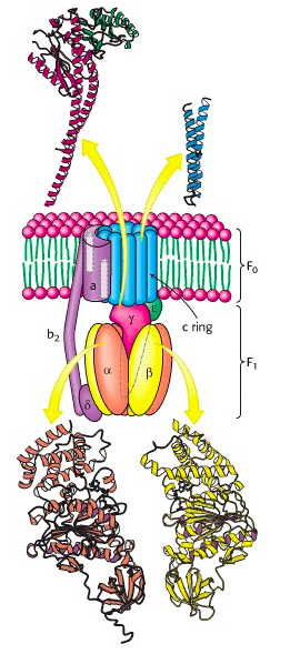
The F1 component consists of 9 subunits, 3 α, 3 β, γ, δ and ε (α3β3γδε, Figure 25.4). Each of the three β subunits has a catalytic site for ATP synthesis. The three α subunits are identical molecules, and the three β subunits are identical molecules. The γ subunit forms a stalk in the centre of the α3β3 complex and acting through ε attaches F1 to the membrane embedded “c” ring of Fo.
The trans-membrane core of Fo is an assembly of multiple copies of the subunit called “c”. The structure of the “c” monomer was determined by NMR spectroscopy; it is a hairpin of hydrophobic alpha helices (Figure 25.5). Multiple c monomers aggregate into a ring. There is still some debate about the number; it seems to vary among different kingdoms of life: “Structural data from yeast, chloroplasts, and bacterial ATPases indicate that subunit c forms rings with 10, 14, and 11 monomers per complex, respectively. Recently (2010) John Walker and colleagues discovered that the mammalian c-ring only contains 8 c subunits!
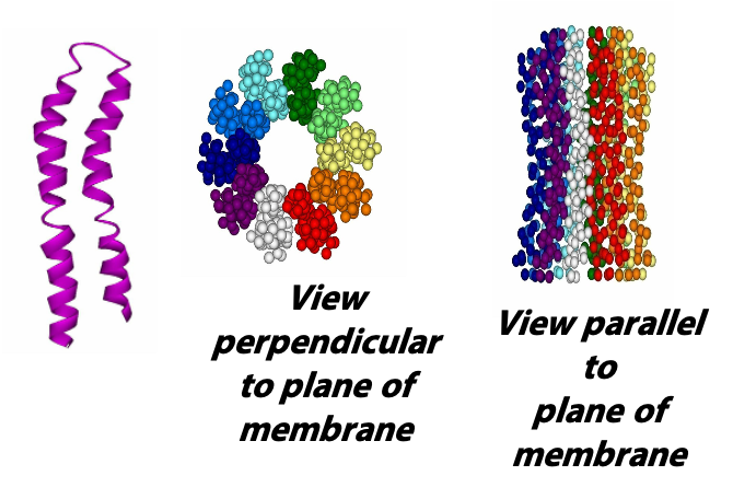
Each c subunit contains a conserved aspartic acid residue (Asp 61) in the middle of one of its helices. The two “b” subunits (acting through δ) associate firmly with α3β3. The “a” subunit resides in the membrane and wraps partially around the c-10 ring and contains two half-channels for the movement of protons.
Kinetic properties of ATP synthase

Paul Boyer did some very clever kinetic experiments (especially using stable isotopes of O) so that he could measure the exchange of phosphate groups among ADP and ATP and Pi (see the textbook by Stryer, Section 18.4, for a good description). What he found was – to his great surprise – that the equilibrium constant for the reaction ADP + Pi → ATP + H2O is close to 1, when the reaction occurs in the active site of the ATP synthase. That is, the free energy change for the reaction, under these conditions, about zero. We know however, that the free energy change for ATP synthesis is large and positive … in solution (Figure 25.6). No catalyst can change that thermodynamic fact. But Boyer managed to measure the equilibrium for the reaction occurring in the active site of the enzyme, without release of the product from the active site. And that is very different, because ATP is bound very, very tightly to the active site. So the free energy profile looks like the one shown in Figure 25.6 at right. Unlike a typical enzyme catalyzed reaction, the energy barrier for ATP synthase is not getting to the transition state but the release of formed ATP from the enzyme.
How does ATP synthase overcome the large energy barrier for the release of ATP?
By building an active site with high affinity for ATP, the enzyme manages to make ATP synthesis easier – but at the inevitable cost of making ATP release from the enzyme more difficult. But ATP bound tightly to the active site of the ATP synthase is of no use to the cell. The ATP has to get released. So, how does the enzyme overcome the large energy barrier for release of ATP?
Boyer proposed that the needed energy is supplied by “rotational catalysis”, and subsequent structural studies have provided spectacular confirmation of this idea. Boyer suggested that the ATP synthase active site cycles between a form that tightly binds ATP and a form that releases ATP. The active site, in a cyclic fashion, is formed, torn apart, and then re-formed to allow the continued synthesis of ATP.
Structural basis for rotational catalysis: each β subunit of F1 can assume 3 different conformations
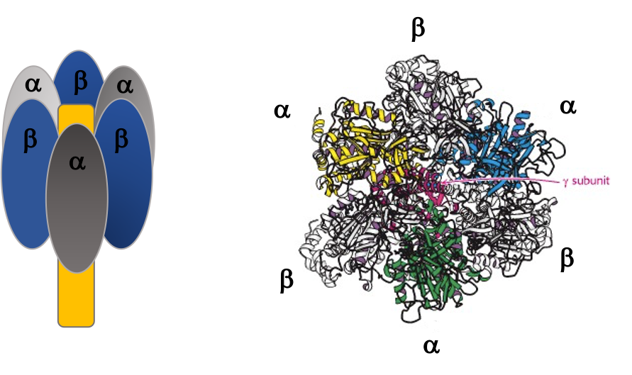
The γ subunit interacts asymmetrically with the α3β3 complex (Figure 25.7). The asymmetric association of the γ subunit causes each of the and subunits to have a different conformation. At a given time each catalytic site is in one of three possible conformations (Figure 25.8). “Loose”, which binds ADP and Pi. “Tight”, which brings about the ready equilibration of ADP + Pi with ATP, with ATP remaining tightly bound to the active site and “Open” which releases ATP and has no bound nucleotides. Each β subunit is able to cycle between these three forms.
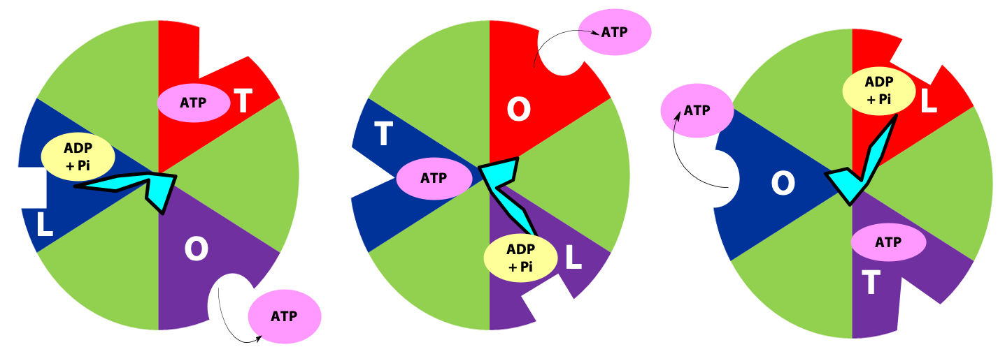
During catalysis, the subunit rotates with respect to the α3β3 complex. With each 120˚ turn of the γ subunit, a different face comes into contact with each β subunit, rotating them between the three different conformations; open, loose and tight. A given β subunit starts in the loose conformation, binding ADP and Pi, then move to the tight form where ATP is formed and finally to the open form where ATP is released.
Rotary mechanism of ATP synthase
The ring of c subunits is the heart of the rotor (see (Figure 25.1). The and subunits rotate along with the ring of c subunits. The a, b, and subunits form the stator arm; they remain fixed with respect to the inner membrane, within which the a and b subunits reside. The b subunits, probably acting via , hold onto the side of the α3β3 complex. Consequently, the α3β3 complex also remains stationary. The ring of c subunits rotates with respect to the stator (a, b, and ), powered by the proton gradient, by a mechanism that we will look at next. The net result is that the subunit turns within the core of the α3β3 complex, changing the conformation of each catalytic site in a cyclic fashion – open, loose, tight, open, loose, tight, open … The enzyme has supplied the energy needed to make ATP via the energy input needed to turn the subunit: pulling apart the active site takes a lot of free energy.
ATP synthase: a rotary engine
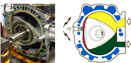
Engineers have built rotary engines, for example those from a Mazda RX7 (Figure 25.9). Any such engine has a stator (the static part) and a rotor (which turns with respect to the stator). In the Mazda engine, as the rotor turns, the three chambers cycle among three states (fueling, combustion/ power stroke, exhaust). The ATP synthase is strikingly similar, but several billion years older and much, much smaller. Instead of being powered by gasoline, it is powered by the proton gradient.
The ATP synthase rotary mechanism
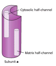
Prof. Wolfgang Jünge, Universität Osnabrück, Germany, proposed this elegant model of the rotary mechanism. It is certainly oversimplified, but is probably correct in essence. The torque (turning force) of the ATP synthase motor is generated by the motion of the ring of c subunits with respect to the “a” subunit that wraps partially around the ring. The “a” subunit forms a channel through which protons flow back across the inner mitochondrial membrane, down their chemical potential gradient. But it is not a continuous channel. In fact, the “a” subunit contains two discrete “half-channels” for protons (Figure 25.10). One half-channel leads from the inter-membrane space side of the membrane into the “a” subunit, and the other half-channel leads from inside of the “a” subunit to the matrix. But there is no direct route from one half-channel to the other one. Instead, protons must jump from the “a” subunit onto the adjacent c subunit.

The c10 ring is held in place by the ionic interaction between Asp61 of “c” and two conserved arginine residues of “a”.
Protons from the inter-membrane space enter the half-channel (the half-channel that connects to the inter-membrane space) and jump from the a subunit onto the closest c subunit (#2 in Figure 25.11).
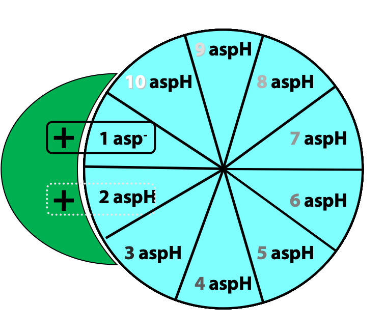
By doing so, they protonate a specific amino acid side-chain (an aspartate) in the c subunit (Figure 25.12.
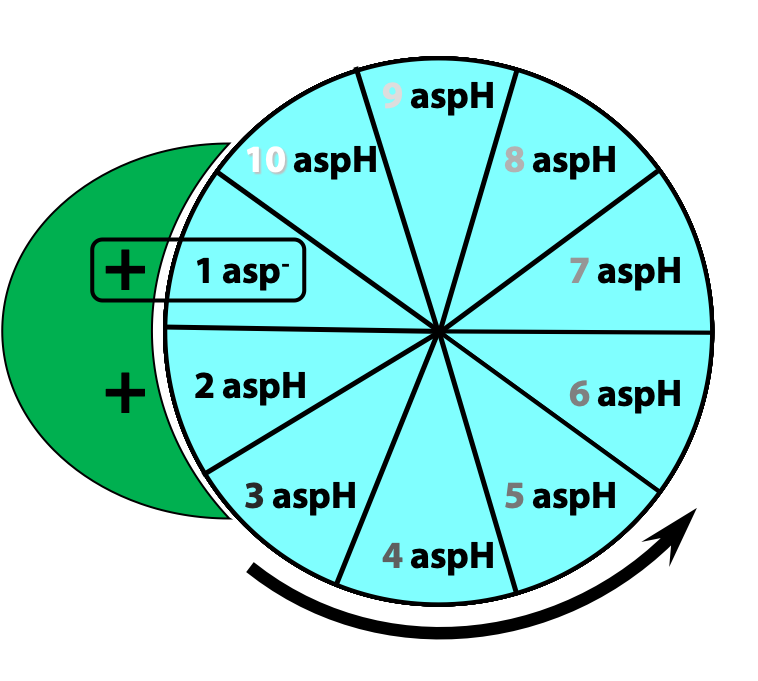
This protonation breaks an ionic attraction between the c subunit aspartate and a conserved arginine residue in the a subunit and so sets the c10 ring free.The c10 ring rotates so that the protonated c subunit moves away from the a subunit and into the hydrophobic milieu of the membrane (Figure 25.13).

Simultaneously, another c subunit is forced into contact with the other half-channel in the a subunit, and a proton is released into the matrix (Figure 25.14)
The c10 ring can only move in one direction: to turn in the opposite direction, we would have to force a negatively-charged c subunit (#1 in the first step) into the hydrophobic milieu of the membrane, but that is highly unfavourable energetically. Thus, two factors dictate the direction of rotation of the c10 ring: the asymmetric orientation of the a subunit half-channels, with respect to the membrane; and the directional proton gradient (the proton-motive force). After ten such protonation/deprotonation events, the c10 ring has performed one complete revolution (Figure 25.15).
The rotation of c leads to the rotation of in the centre of α3β3. One full rotation causes each subunit to cycle through all three possible conformations, leading to the synthesis and release of three ATPs.
The P/O ratio of oxidative phosphorylation, in light of the mechanism of ATP synthesis
The P/O ratio is the number of moles of ATP synthesized per mole of O reduced to water.
Look at the following calculation: one NADH delivers exactly one pair of electrons to the ETC. These two electrons are ultimately transferred to O2 to give H2O; and, during the process, ten protons are pumped out of the matrix. It takes exactly ten protons to turn the ATP synthase through one full revolution which produces three ATP. So, the P/O ratio for NADH must be exactly 3.00!
Well, that’s a reasonable argument, but the calculation overlooks a few things. For example: Some of the proton gradient energy is used for purposes other than ATP synthesis – notably, to power the transport of solutes across the inner mitochondrial membrane. One proton per ATP synthesized is used to pump Pi into the matrix (via the phosphate translocase symporter; see Stryer Fig. 18.40). The proton / energy requirement for Pi transport, among other factors, contribute to P/O being < 3.0, as was stated earlier.