3 The Design and Construction Process
3.1 Design and Construction as an Integrated System
In the planning of facilities, it is important to recognize the close relationship between design and construction. These processes can best be viewed as an integrated system. Broadly speaking, design is a process of creating the description of a new facility, usually represented by detailed plans, drawings and specifications; construction planning is a process of identifying activities and resources required to make the design a physical reality. Hence, construction is the implementation of a design envisioned by architects and engineers. In both design and construction, numerous operational tasks must be performed with a variety of precedence and other relationships among the different tasks.
Several characteristics are unique to the planning of constructed facilities and should be kept in mind even at the very early stage of the project life cycle. These include the following:
- Nearly every facility is custom designed and constructed, and often requires a long time to complete.
- Both the design and construction of a facility must satisfy the conditions peculiar to a specific site.
- Because each project is site specific, its execution is influenced by natural, social and other locational conditions such as weather, labor supply, local building codes, etc.
- Since the service life of a facility is long, the anticipation of future requirements is inherently difficult.
- Because of technological complexity and market demands, changes of design plans during construction are not uncommon.
In an integrated system, the planning for both design and construction can proceed almost simultaneously, examining various alternatives which are desirable from both viewpoints and thus eliminating the necessity of extensive revisions under the guise of value engineering. Furthermore, the review of designs with regard to their constructability can be carried out as the project progresses from planning to design. For example, if the sequence of assembly of a structure and the critical loadings on the partially assembled structure during construction are carefully considered as a part of the overall structural design, the impacts of the design on construction falsework and on assembly details can be anticipated. However, if the design professionals are expected to assume such responsibilities, they must be rewarded for sharing the risks as well as for undertaking these additional tasks. Similarly, when construction contractors are expected to take over the responsibilities of engineers, such as devising a very elaborate scheme to erect an unconventional structure, they too must be rewarded accordingly. As long as the owner does not assume the responsibility for resolving this risk-reward dilemma, the concept of a truly integrated system for design and construction cannot be realized.
It is interesting to note that European owners are generally more open to new technologies and to share risks with designers and contractors. In particular, they are more willing to accept responsibilities for the unforeseen subsurface conditions in geotechnical engineering. Consequently, the designers and contractors are also more willing to introduce new techniques in order to reduce the time and cost of construction. In European practice, owners typically present contractors with a conceptual design, and contractors prepare detailed designs, which are checked by the owner’s engineers. Those detailed designs may be alternate designs, and specialty contractors may also prepare detailed alternate designs. This is also a practice followed by many US DOTs and Canadian provincial ministries of transportation for highway construction projects.
Example 3-1: Responsibility for Shop Drawings
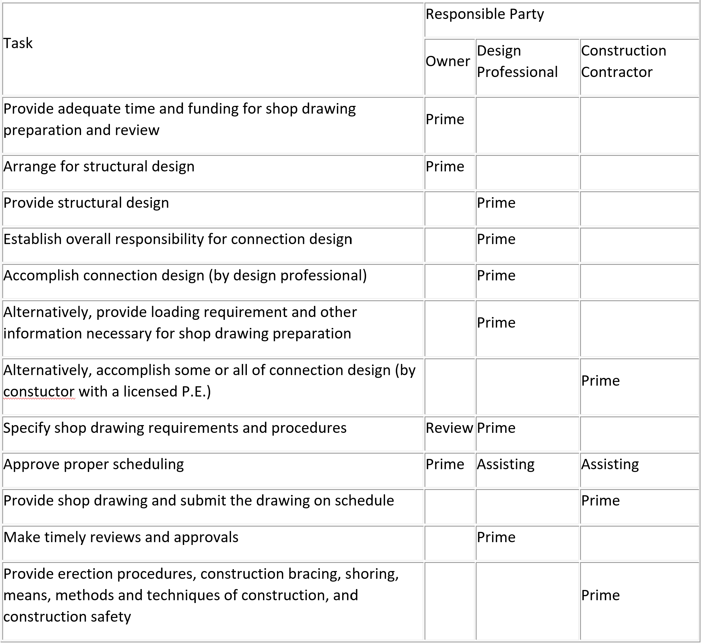
Shop drawings represent the assembly details for erecting a structure which should reflect the intent and rationale of the original structural design. They are prepared by the construction contractor and reviewed by the design professional. However, since the responsibility for preparing shop drawings was traditionally assigned to construction contractors, design professionals took the view that the review process was advisory and assumed no responsibility for their accuracy. This justification was ruled unacceptable by a court in connection with the walkway failure at the Hyatt Hotel in Kansas City in 1985. In preparing the ASCE Manual of Professional Practice for Quality in the Constructed Project, the responsibilities for preparation of shop drawings proved to be the most difficult to develop. [1] The reason for this situation is not difficult to fathom since the responsibilities for the task are diffused, and all parties must agree to the new responsibilities assigned to each in the recommended risk-reward relations shown in Table 3-1.
Traditionally, the owner is not involved in the preparation and review of shop drawings, and perhaps is even unaware of any potential problems. In the recommended practice, the owner is required to take responsibility for providing adequate time and funding, including approval of scheduling, in order to allow the design professionals and construction contractors to perform satisfactorily.
Table 3-1 Recommended Responsibility for Shop Drawings
In “Design and Construction of Structural Steel Work” (NAC Executive Insights – Technical Fundamentals for Design and Construction, December 3, 2021) Tatum et al note that their may be several (rather than the three in the example above) roles in steel construction, including:
- The structural engineer is responsible for the overall structural design.
- The designer sets design criteria, designs the structure, and produces specifications and drawings.
- The detailer prepares shop drawings using design drawings, standard details for connections, and, importantly, has knowledge of operations for fabrication and erection.
- The general contractor (GC) is responsible for the overall construction of the project. The GC’s responsibility also includes coordination of steel erection with the civil, concrete, mechanical, electrical, and plumbing (MEP), and architectural work.
- The field, project, or construction engineer provides construction input, reviews shop drawings, designs temporary steel, and develops detailed erection plans and drawings. They typically also prepare the schedule for arrival of the steel and the equipment needed. Another of their key activities is checking the site for stability of lifting equipment and safety.
- The steel fabricator’s responsibility varies by region. In the U.S., fabrication is typically combined with a steel erector on the West Coast. The fabricator orders standard steel shapes from supplier, may design connections based on area practice, fabricates custom members for the project, and delivers fabricated members in a sequence that supports the erection plan.
- The steel erector is responsible for the means, methods, and safety of erecting the structural steel frame. The erector prepares the erection plan, receives the steel, erects and connects (steel decking is typically by others in California), and provides temporary supports and safety protection.
Example 3-2:Model Metro Project in Milan, Italy [2]
Under Italian law, unforeseen subsurface conditions are the owner’s responsibility, not the contractor’s. This is a striking difference from U.S. construction practice where changed conditions clauses and claims and the adequacy of prebid site investigations are points of contention. In effect, the Italian law means that the owner assumes those risks. But under the same law, a contractor may elect to assume the risks in order to lower the bid price and thereby beat the competition.
According to the Technical Director of Rodio, the Milan-based contractor which was heavily involved in the grouting job for tunneling in the Model Metro project in Milan, Italy, there are two typical contractual arrangements for specialized subcontractor firms such as theirs. One is to work on a unit price basis with no responsibility for the design. The other is what he calls the “nominated subcontractor” or turnkey method: prequalified subcontractors offer their own designs and guarantee the price, quality, quantities, and, if they wish, the risks of unforeseen conditions.
At the beginning of the Milan metro project, the Rodio contract ratio was 50/50 unit price and turnkey. The firm convinced the metro owners that they would save money with the turnkey approach, and the ratio became 80% turnkey. What’s more, in the work packages where Rodio worked with other grouting specialists, those subcontractors paid Rodio a fee to assume all risks for unforeseen conditions.
Under these circumstances, it was critical that the firm should know the subsurface conditions as precisely as possible, which was a major reason why the firm developed a computerized electronic sensing program to predict stratigraphy and thus control grout mixes, pressures and, most important, quantities.
For an executive level perspective read the following reports on Construction Driven Design:
Management of Engineering in Design/Build
Design/build project delivery changes the nature of the relationship between the project’s constructor (design/build contractor) and the engineer. This changed relationship has a myriad of legal, commercial, and risk implications. Importantly, it changes the very nature, sequencing, and emphasis of the design process.
The Design and Construction of the Governor Mario M. Cuomo Bridge
The Governor Mario M. Cuomo Bridge is a 3-mile long, twin bridge crossing of the Tappan Zee portion of the Hudson River north of New York City.
Constructability Review Before Design Commences
Constructability reviews are a series of meetings, generally corresponding to and aligning with a project’s stage-gate process.
Design-build is a growing project delivery model especially in the delivery of large complex projects.
3.2 Innovation and Technological Feasibility
The planning for a construction project begins with the generation of concepts for a facility which will meet market demands and owner needs. Innovative concepts in design are highly valued not for their own sake but for their contributions to reducing costs and to the improvement of aesthetics, comfort or convenience as embodied in a well-designed facility. However, the constructor as well as the design professionals must have an appreciation and full understanding of the technological complexities often associated with innovative designs in order to provide a safe and sound facility. Since these concepts are often preliminary or tentative, screening studies are carried out to determine the overall technological viability and economic attractiveness without pursuing these concepts in great detail. Because of the ambiguity of the objectives and the uncertainty of external events, screening studies call for uninhibited innovation in creating new concepts and judicious judgment in selecting the appropriate ones for further consideration.
One of the most important aspects of design innovation is the necessity of communication in the design/construction partnership. In the case of bridge design, it can be illustrated by the following quotation from Lin and Gerwick concerning bridge construction: [3]
The great pioneering steel bridges of the United States were built by an open or covert alliance between designers and constructors. The turnkey approach of designer-constructor has developed and built our chemical plants, refineries, steel plants, and nuclear power plants. It is time to ask, seriously, whether we may not have adopted a restrictive approach by divorcing engineering and construction in the field of bridge construction.
If a contractor-engineer, by some stroke of genius, were to present to design engineers today a wonderful new scheme for long span prestressed concrete bridges that made them far cheaper, he would have to make these ideas available to all other constructors, even limiting or watering them down so as to “get a group of truly competitive bidders.” The engineer would have to make sure that he found other contractors to bid against the ingenious innovator.
If an engineer should, by a similar stroke of genius, hit on such a unique and brilliant scheme, he would have to worry, wondering if the low bidder would be one who had any concept of what he was trying to accomplish or was in any way qualified for high class technical work.
Innovative design concepts must be tested for technological feasibility. Three levels of technology are of special concern: technological requirements for operation or production, design resources and construction technology. The first refers to the new technologies that may be introduced in a facility which is used for a certain type of production such as chemical processing or nuclear power generation. The second refers to the design capabilities that are available to the designers, such as new computational methods or new materials. (Many large engineering firms are profitable mainly because of proprietary in-house intellectual property in this regard.) The third refers to new technologies which can be adopted to construct the facility, such as new equipment or new construction methods.
A new facility may involve complex new technology for operation in hostile environments such as severe climate or restricted accessibility. Large projects with unprecedented demands for resources such as labor supply, material and infrastructure may also call for careful technological feasibility studies. Major elements in a feasibility study on production technology should include, but are not limited to, the following:
- Project type as characterized by the technology required, such as synthetic fuels, petrochemicals, nuclear power plants, etc.
- Project size in dollars, design engineer’s hours, construction labor hours, etc.
- Design, including sources of any special technology which require licensing agreements.
- Project location which may pose problems in environmental protection, labor productivity and special risks.
An example of innovative design for operation and production is the use of entropy concepts for the design of integrated chemical processes. Simple calculations can be used to indicate the minimum energy requirements and the least number of heat exchange units to achieve desired objectives. The result is a new incentive and criterion for designers to achieve more effective designs. Numerous applications of the new methodology has shown its efficacy in reducing both energy costs and construction expenditures. [4] This is a case in which innovative design is not a matter of trading-off operating and capital costs, but better designs can simultaneously achieve improvements in both objectives.
The choice of construction technology and method involves both strategic and tactical decisions about appropriate technologies and the best sequencing of operations. For example, the extent to which prefabricated facility components will be used represents a strategic construction decision. In turn, prefabrication of components might be accomplished off-site in existing manufacturing facilities or a temporary, on-site fabrication plant might be used. For an example, refer again to The Design and Construction of the Governor Mario M. Cuomo Bridge. Another example of a strategic decision is whether to install mechanical equipment in place early in the construction process or at an intermediate stage. Strategic decisions of this sort should be integrated with the process of facility design in many cases. At the tactical level, detailed decisions about how to accomplish particular tasks are required, and such decisions can often be made in the field.
Construction planning should be a major concern in the development of facility designs, in the preparation of cost estimates, and in forming bids by contractors. Unfortunately, planning for the construction of a facility is often treated as an after thought by design professionals. This contrasts with manufacturing practices in which the assembly of devices is a major concern in design. Design to insure ease of assembly or construction should be a major concern of engineers and architects. As the Business Roundtable noted, “All too often chances to cut schedule time and costs are lost because construction operates as a production process separated by a chasm from financial planning, scheduling, and engineering or architectural design. Too many engineers, separated from field experience, are not up to date about how to build what they design, or how to design so structures and equipment can be erected most efficiently.” [5]
For some in-depth descriptions of best practices for thoroughly considering innovation and technological feasibility at the project design stage in large construction projects, visit the National Academy of Construction site for the following reports:
This Executive Insight focuses on achieving improved capital efficiency in large capital asset projects through the adoption of an expanded basis of design that considers all aspects of a capital asset’s life cycle. In many projects today, the basis of design (BOD) largely encompasses the engineering parameters required to meet the owner’s project requirements (OPR).
Know What You Are Trying to Accomplish: The Primacy of the Scope Baseline
This Executive Insight focuses on the scope baseline and suggests its primacy among the three baselines. An incomplete scope will, by definition, result in incomplete or inaccurate schedules and estimates.
Design review ensures the effective transformation of the owner’s project requirements (OPR).
Example 3-3: Innovative use of structural frames for buildings [6]
The structural design of skyscrapers offers an example of innovation in overcoming the barrier of high costs for tall buildings by making use of new design capabilities. A revolutionary concept in skyscraper design was introduced in the 1960’s by Fazlur Khan who argued that, for a building of a given height, there is an appropriate structural system which would produce the most efficient use of the material.
Before 1965, most skyscrapers were steel rigid frames. However, Fazlur Khan believed that it was uneconomical to construct all office buildings of rigid frames and proposed an array of appropriate structural systems for steel buildings of specified heights as shown in Figure 3-1. By choosing an appropriate structural system, an engineer can use structural materials more efficiently. For example, the 60-story Chase Manhattan Building in New York used about 60 pounds per square foot of steel in its rigid frame structure, while the 100-story John Hancock Center in Chicago used only 30 pounds per square foot for a trusted tube system. At the time the Chase Manhattan Building was constructed, no bracing was used to stiffen the core of a rigid frame building because design engineers did not have the computing tools to do the complex mathematical analysis associated with core bracing.
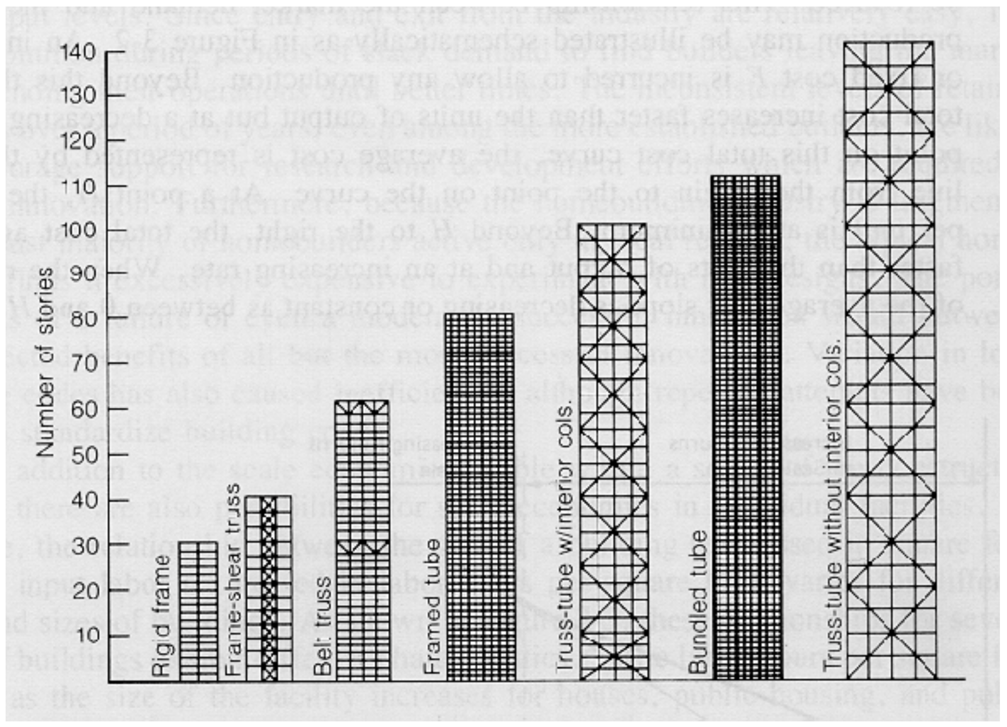
Figure 3-1: Proposed Structural System for Steel Buildings
(Reprinted with permission from Civil Engineering, May 1983)
3.3 Innovation and Economic Feasibility
Innovation is often regarded as the engine which can introduce construction economies and advance labor productivity. This is obviously true for certain types of innovations in industrial production technologies, design capabilities, and construction equipment and methods. However, there are also limitations due to the economic infeasibility of such innovations, particularly in the segments of the construction industry which are more fragmented and permit ease of entry, as in the construction of residential housing.
Market demand and firm size play an important role in this regard. If a builder is to construct a larger number of similar units of buildings, the cost per unit may be reduced. This relationship between the market demand and the total cost of production may be illustrated schematically as in Figure 3-2. An initial threshold or fixed cost F is incurred to allow any production. Beyond this threshold cost, total cost increases faster than the units of output but at a decreasing rate. At each point on this total cost curve, the average cost is represented by the slope of a line from the origin to the point on the curve. At a point H, the average cost per unit is at a minimum. Beyond H to the right, the total cost again increases faster than the units of output and at an increasing rate. When the rate of change of the average cost slope is decreasing or constant as between 0 and H on the curve, the range between 0 and H is said to be increasing return to scale; when the rate of change of the average cost slope is increasing as beyond H to the right, the region is said to be decreasing return to scale. Thus, if fewer than h units are constructed, the unit price will be higher than that of exactly h units. On the other hand, the unit price will increase again if more than h units are constructed.
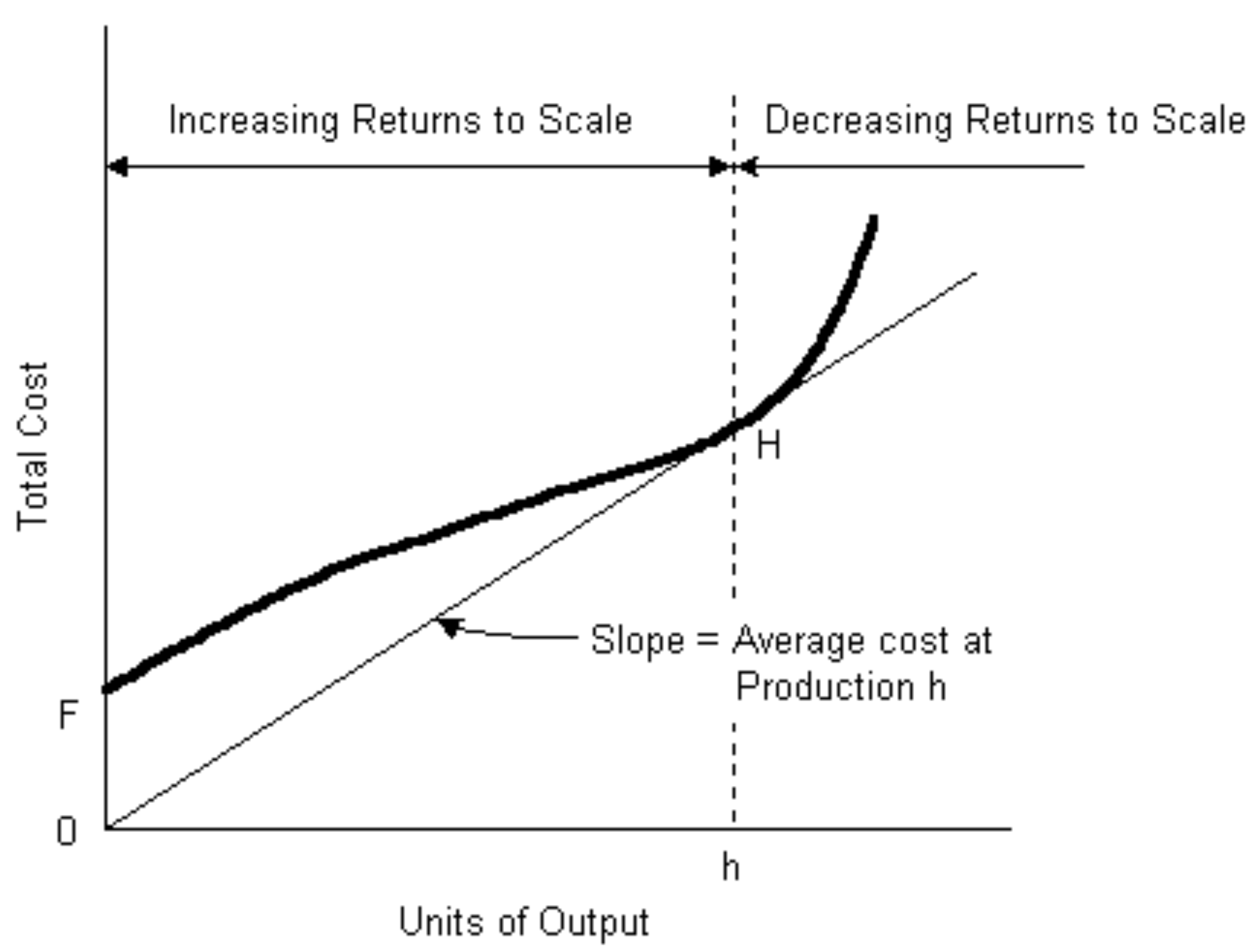
Figure 3-2: Market Demand and Total Cost Relationship
Nowhere is the effect of market demand and total cost more evident than in residential housing. [7] The housing segment in the last few decades accepted many innovative technical improvements in building materials and equipment which were promoted by suppliers. Examples include high r-factor windows, heat-pumps, and intelligent building control systems (for heating, ventilation, air-conditioning, lighting, etc.). Since suppliers provide products to a large number of homebuilders and others, they are in a better position to exploit production economies of scale and to support new product development. Homebuilders themselves were not as successful in making the most fundamental form of innovation, which encompasses changes in the technological process of homebuilding by shifting the mixture of labor and material inputs, such as substituting large scale off-site prefabrication for on-site assembly. However, the situation has been changing recently (2020 onward). In Getting Ready for 2030: A Roadmap for Offsite Construction (Construction Industry Institute Research Team 371, Onsite versus Offsite Construction – The Impact of Offsite Construction on the Workforce. Final Report 371, September 2021), based on a survey of 100 industry professionals, it was concluded that offsite construction (prefabrication and modularization) will become the norm rather than the exception. The current average share of offsite construction, 33.64%, is expected to grow substantially, reaching an average share of 54.9% by 2030. This represents exponential industry growth (5-8 % CAGR depending on the source). McKinsey & Company claim “Modular construction can cut schedule by 20–50 percent and construction costs by 20 percent”. Change is happening.
Nonetheless, there remain several major barriers to innovation in the technological process of homebuilding, including demand instability, variation in local building codes, permitting, and financing plant investments. Since market demand for new homes follows demographic trends and other socio-economic conditions (as described in chapter 1), the variation in home building has been anything but regular. The profitability of the homebuilding industry has closely matched aggregate output levels. Since entry and exist from the industry are relatively easy, it is not uncommon during periods of slack demand to find builders leaving the market or suspending their operations until better times. The inconsistent levels of retained earnings over a period of years, even among the more established builders, discourage support for research and development efforts which are required to nurture innovation. Furthermore, because the homebuilding industry is fragmented with a vast majority of homebuilders active only in local regions, the typical homebuilder finds it excessively expensive to experiment with new designs. The potential costs of a failure or even a moderately successful innovation would outweigh the expected benefits of all but the most successful innovations.
In addition to the scale economies visible within the residential sector of the construction market, there are also possibilities for scale economies in an individual facility. For example, the relationship between the size of a building (expressed in square feet) and the input labor (expressed in labor hours per square foot) varies for different types and sizes of buildings. As shown in Figure 3-3, these relationships for several types of buildings exhibit different characteristics. [8] The labor hours per square foot decline as the size of facility increases for houses, public housing and public buildings. However, the labor hours per square foot almost remains constant for all sizes of school buildings and increases as the size of a hospital facility increases. These relationships have not fundamentally changed since the study cited for Figure 3-3.
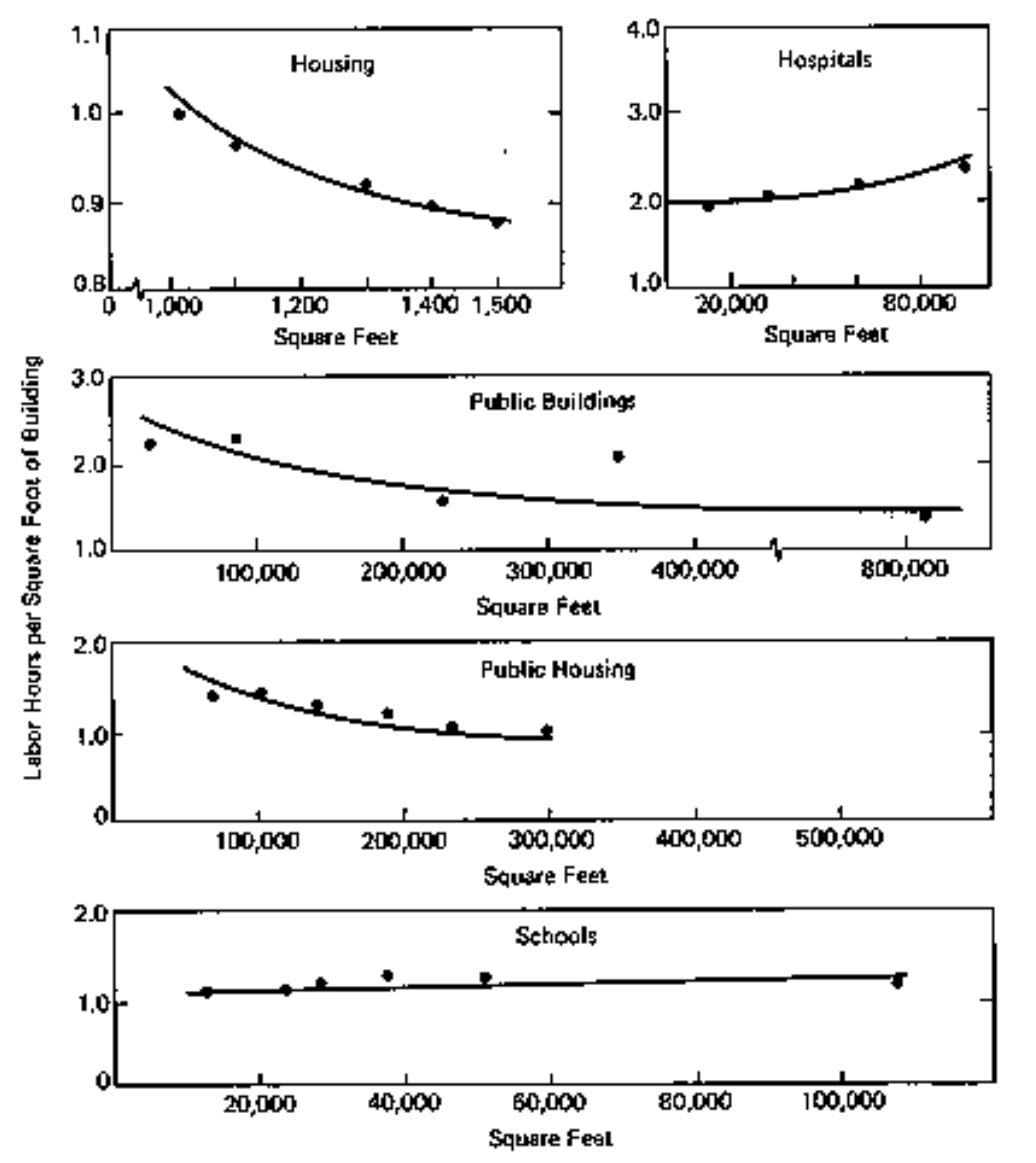
Figure 3-3: Illustrative Relationships between Building Size and Input Labor by Types of Building
(Reprinted with permission from P.J. Cassimatis, Economics of the Construction Industry,
The National Industry Conference Board, SEB, No. 111, 1969, p.53)
Example 3-4: Use of new materials
An early article on warm asphalt notes its performance potential and its impact on lowering embodied energy substantially (warm asphalt is now widely in use). (S.D. Capitão, L.G. Picado-Santos, F. Martinho, Pavement engineering materials: Review on the use of warm-mix asphalt, Construction and Building Materials, Volume 36, 2012, Pages 1016-1024, ISSN 0950-0618, https://doi.org/10.1016/j.conbuildmat.2012.06.038 . ) The abstract is quoted below:
“Warm asphalt mixtures have been used worldwide aiming at saving energy and reducing emissions throughout the production process, without decreasing the in-service performance. This has been achieved with wax additives, chemical additives and foaming techniques. Benefits and drawbacks are mentioned in the literature for each process. This paper is a review of the main aspects involved in WMA technology, including constituent materials, mix design and mechanical performance issues, as well as technological specificities. Some discussion associated to life-cycle analysis is also considered. In the view of the literature review, it can be stated that WMA is a very interesting technology, able to contribute to achieve environmental objectives along with acceptable performance. WMA processes themselves require some additional complexity that must be considered by the players involved.”
Example 3-5: Green Buildings
“Green”, “net-zero” and related terms refer to a revolution in the construction industry that acknowledges the impact on sustainability of operating and embodied energy costs of capital facilities such as buildings. In a research program announced in 2022 by the National Research Council of Canada, $700M CDN was budgeted for the Construction Research Centre at the National Research Council of Canada (NRC) to address one of the biggest challenges facing Canada’s construction sector: decarbonization. In their web site they note that:
“The construction sector is a significant emitter of greenhouse gases (GHGs), from the production of construction materials to the heating, cooling and maintenance of existing buildings and infrastructure. To achieve Canada’s emission reduction targets by 2050, new low carbon technologies and tools are needed to support further advancements in the construction sector.
Together with academia, industry and governments, the NRC is applying its R&D expertise to support the development and deployment of low carbon construction solutions through the new Platform to Decarbonize the Construction Sector at Scale.”
3.4 Design Methodology
While the conceptual design process may be formal or informal, it can be characterized by a series of actions: formulation, analysis, search, decision, specification, and modification. However, at the early stage in the development of a new project, these actions are highly interactive as illustrated in Figure 3-4. [11] Many iterations of redesign are expected to refine the functional requirements, design concepts and financial constraints, even though the analytic tools applied to the solution of the problem at this stage may be very crude.
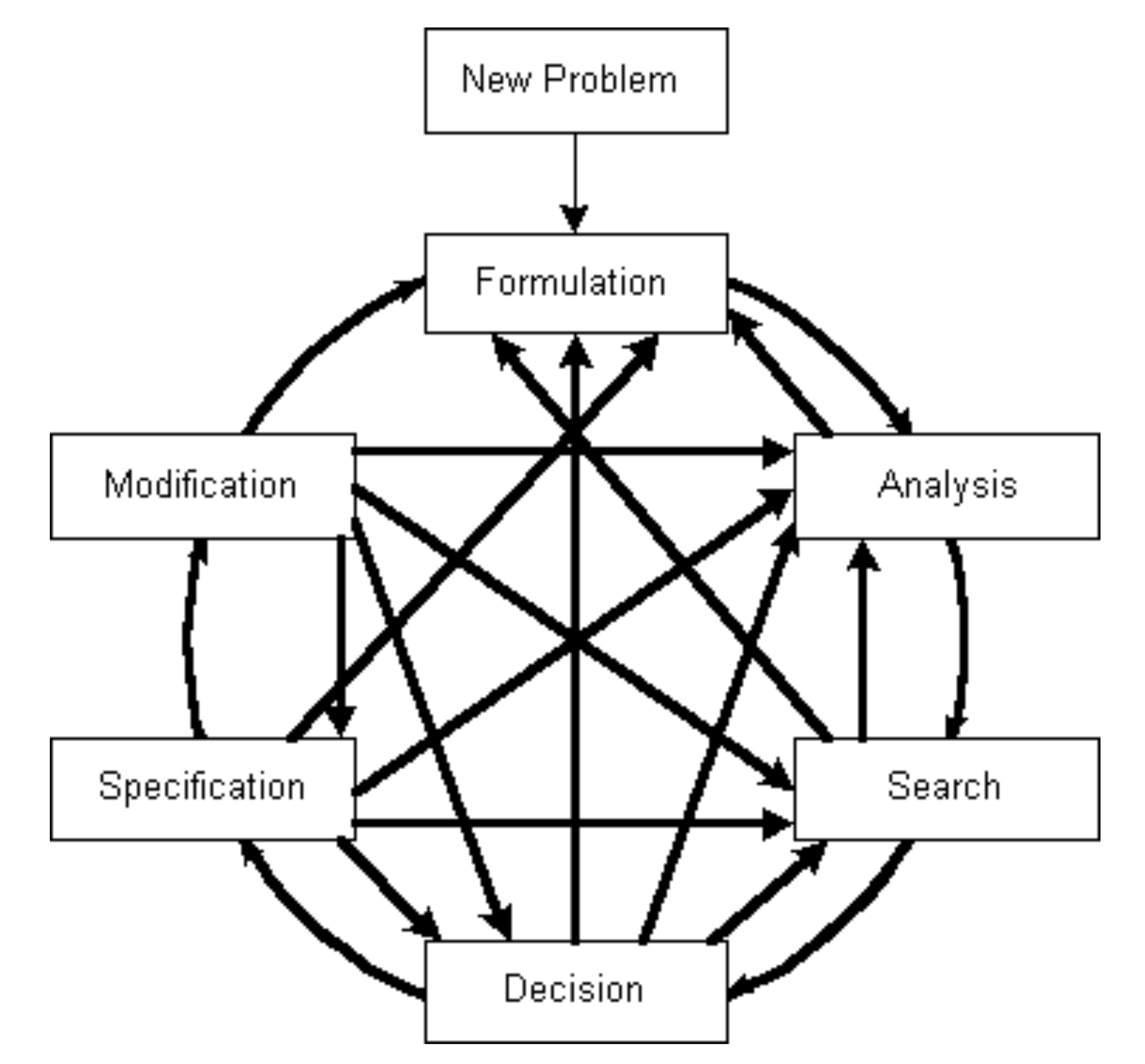
Figure 3-4: Conceptual Design Process
(Adapted with permission from R.W. Jensen and C.C. Tonies, Software Engineering,
Prentice Hall, Englewood Cliffs, NJ, 1979, p.22)
The series of actions taken in the conceptual design process may be described as follows:
- Formulation refers to the definition or description of a design problem in broad terms through the synthesis of ideas describing alternative facilities.
- Analysis refines the problem definition or description by separating important from peripheral information and by pulling together the essential detail. Interpretation and prediction are usually required as part of the analysis.
- Search involves gathering a set of potential solutions for performing the specified functions and satisfying the user requirements.
- Decision means that each of the potential solutions is evaluated and compared to the alternatives until the best solution is obtained.
- Specification is to describe the chosen solution in a form which contains enough detail for implementation.
- Modification refers to the change in the solution or re-design if the solution is found to be wanting or if new information is discovered in the process of design.
As the project moves from conceptual planning to detailed design, the design process becomes more formal. In general, the actions of formulation, analysis, search, decision, specification and modification still hold, but they represent specific steps with less random interactions in detailed design. The design methodology thus formalized can be applied to a variety of design problems. For example, the analogy of the schematic diagrams of the structural design process and of the computer program development process is shown in Figure 3-5 [12].
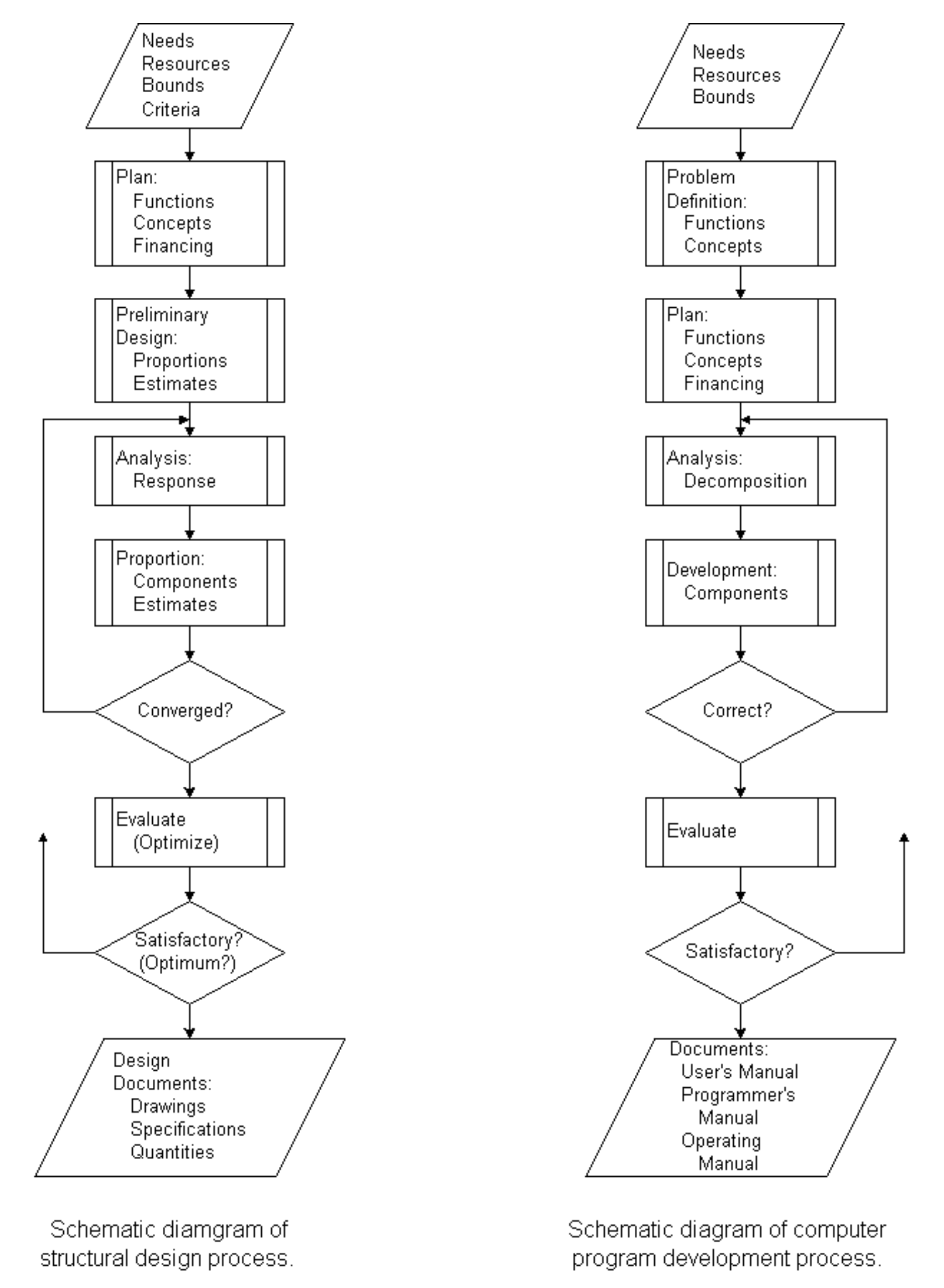
Figure 3-5: An Analogy Between Structural Design and Computer Program Development Process
(Reprinted with permission from E.H. Gaylord and C. N. Gaylord, eds., Structural Engineering Handbook,
2nd Ed., McGraw-Hill Book Company, New York, 1979.)
The basic approach to design relies on decomposition and integration. Since design problems are large and complex, they have to be decomposed to yield subproblems that are small enough to solve. There are numerous alternative ways to decompose design problems, such as decomposition by functions of the facility, by spatial locations of its parts, or by links of various functions or parts. Solutions to subproblems must be integrated into an overall solution. The integration often creates conceptual conflicts which must be identified and corrected. A hierarchical structure with an appropriate number of levels may be used for the decomposition of a design problem to subproblems. For example, in the structural design of a multistory building, the building may be decomposed into floors, and each floor may in turn be decomposed into separate areas. Thus, a hierarchy representing the levels of building, floor and area is formed.
Different design styles may be used. The adoption of a particular style often depends on factors such as time pressure or available design tools, as well as the nature of the design problem. Examples of different styles are:
- Top-down design. Begin with a behavior description of the facility and work towards descriptions of its components and their interconnections. This would be appropriate for a process facility.
- Bottom-up design. Begin with a set of components, and see if they can be arranged to meet the behavior description of the facility. This would be appropriate for a cultural or community center.
The design of a new facility often begins with the search of the files for a design that comes as close as possible to the one needed. The design process is guided by accumulated experience and intuition in the form of heuristic rules to find acceptable solutions. As more experience is gained for this particular type of facility, it often becomes evident that parts of the design problem are amenable to rigorous definition and algorithmic solution. Even formal optimization methods may be applied to some parts of the problem.
3.5 Functional Design
The objective of functional design for a proposed facility is to treat the facility as a complex system of interrelated spaces which are organized systematically according to the functions to be performed in these spaces in order to serve a collection of needs. The arrangement of physical spaces can be viewed as an iterative design process to find a suitable floor plan to facilitate the movement of people and goods associated with the operations intended.
A designer often relies on a heuristic approach, i.e., applying selected rules or strategies serving to stimulate the investigation in search for a solution. The heuristic approach used in arranging spatial layouts for facilities is based generally on the following considerations:
- identification of the goals and constraints for specified tasks,
- determination of the current state of each task in the iterative design process,
- evaluation of the differences between the current state and the goals,
- means of directing the efforts of search towards the goals on the basis of past experience.
Hence, the procedure for seeking the goals can be recycled iteratively in order to make tradeoffs and thus improve the solution of spatial layouts.
Consider, for example, an integrated functional design for a proposed hospital. [13] Since the responsibilities for satisfying various needs in a hospital are divided among different groups of personnel within the hospital administrative structure, a hierarchy of functions corresponding to different levels of responsibilities is proposed in the systematic organization of hospital functions. In this model, the functions of a hospital system are decomposed into a hierarchy of several levels:
- Hospital–conglomerate of all hospital services resulting from top policy decisions,
- Division–broadly related activities assigned to the same general area by administrative decisions,
- Department–combination of services delivered by a service or treatment group,
- Suite–specific style of common services or treatments performed in the same suite of rooms,
- Room–all activities that can be carried out in the same internal environment surrounded by physical barriers,
- Zone–several closely related activities that are undertaken by individuals,
- Object–a single activity associated with an individual.
In the integrated functional design of hospitals, the connection between physical spaces and functions is most easily made at the lowest level of the hierarchy, and then extended upward to the next higher level. For example, a bed is a physical object immediately related to the activity of a patient. A set of furniture consisting of a bed, a night table and an armchair arranged comfortably in a zone indicates the sphere of private activities for a patient in a room with multiple occupancy. Thus, the spatial representation of a hospital can be organized in stages starting from the lowest level and moving to the top. In each step of the organization process, an element (space or function) under consideration can be related directly to the elements at the levels above it, to those at the levels below it, and to those within the same level.
Since the primary factor relating spaces is the movement of people and supplies, the objective of arranging spaces is the minimization of movement within the hospital. On the other hand, the internal environmental factors such as atmospheric conditions (pressure, temperature, relative humidity, odor and particle pollution), sound, light and fire protection produce constraining effects on the arrangement of spaces since certain spaces cannot be placed adjacent to other spaces because of different requirements in environmental conditions. The consideration of logistics is important at all levels of the hospital system. For example, the travel patterns between objects in a zone or those between zones in a room are frequently equally important for devising an effective design. On the other hand, the adjacency desirability matrix based upon environmental conditions will not be important for organization of functional elements below the room level since a room is the lowest level that can provide a physical barrier to contain desirable environmental conditions. Hence, the organization of functions for a new hospital can be carried out through an interactive process, starting from the functional elements at the lowest level that is regarded as stable by the designer, and moving step by step up to the top level of the hierarchy. Due to the strong correlation between functions and the physical spaces in which they are performed, the arrangement of physical spaces for accommodating the functions will also follow the same iterative process. Once a satisfactory spatial arrangement is achieved, the hospital design is completed by the selection of suitable building components which complement the spatial arrangement.
Example 3-6: Top-down design style
In the functional design of a hospital, the designer may begin with a “reference model”, i.e. the spatial layouts of existing hospitals of similar size and service requirements. On the basis of past experience, spaces are allocated to various divisions as shown schematically in Figure 3-6. The space in each division is then divided further for various departments in the division, and all the way down the line of the hierarchy. In every step along the way, the pertinent information of the elements immediately below the level under consideration will be assessed in order to provide input for making necessary adjustments at the current level if necessary. The major drawback of the top-down design style is that the connection between physical spaces and functions at lower levels cannot be easily anticipated. Consequently, the new design is essentially based on the intuition and experience of the designer rather than an objective analysis of the functions and space needs of the facility. Its greatest attraction is its simplicity which keeps the time and cost of design relatively low.
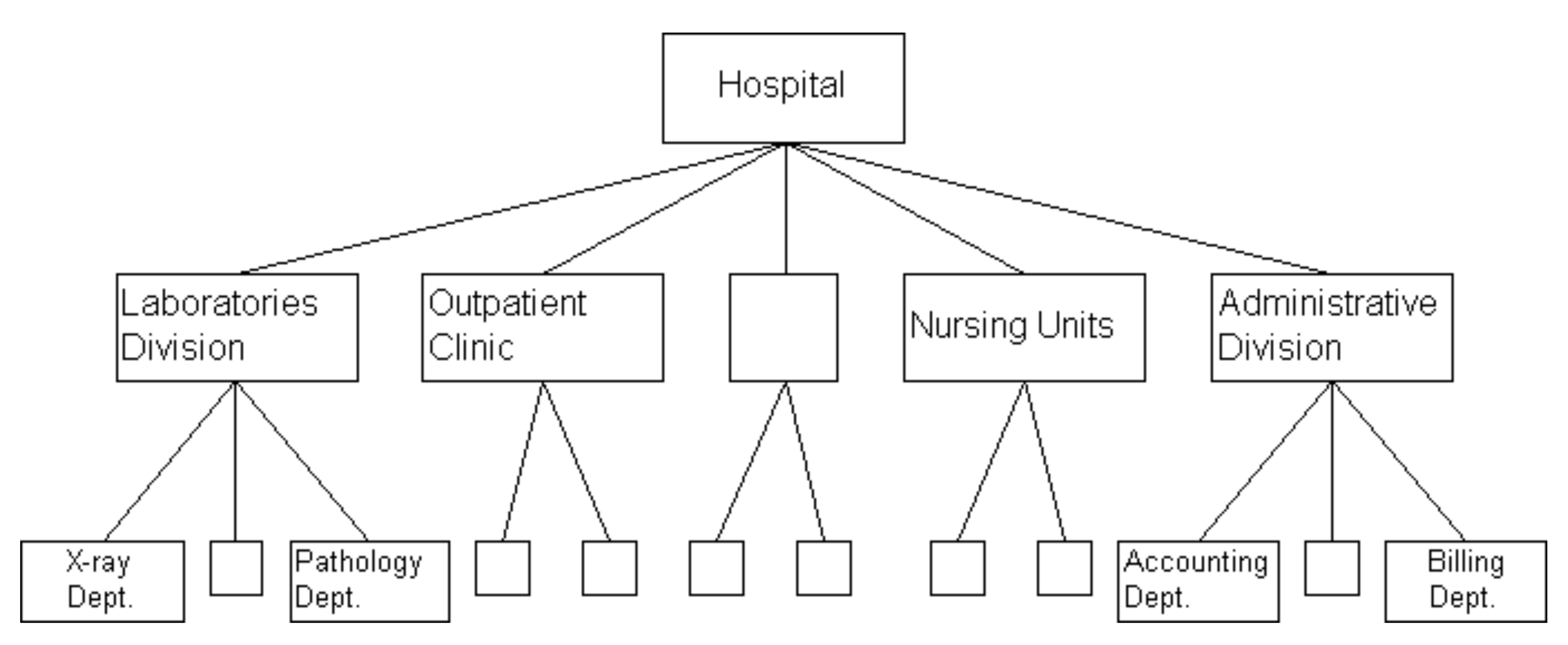
Figure 3-6: A Model for Top-Down Design of a Hospital
Example 3-7: Bottom-up design style
A multi-purpose examination suite in a hospital is used as an illustration of bottom-up design style. In Figure 3-7, the most basic elements (furniture) are first organized into zones which make up the room. Thus the size of the room is determined by spatial layout required to perform the desired services. Finally, the suite is defined by the rooms which are parts of the multi-purpose examination suite.
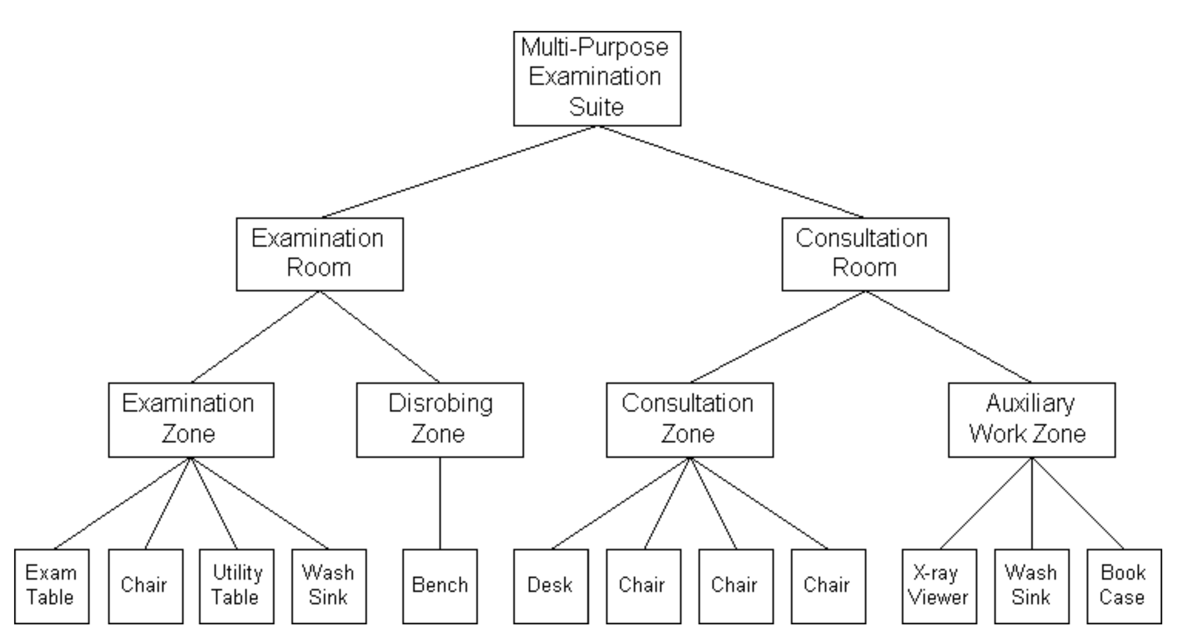
Figure 3-7: A Model for Bottom-up design of an Examination Suite
In the last decade, massive computing power, AI tools, and building physics plug-ins for BIM software such as Revit have been used to augment the preceding basic design approaches to create a new practice called “generative design”. A well described example with excellent illustrations is the design of the Autodesk Toronto Office, c. 2017. They describe a framework that consists of three main components:
- generate a wide design space of possible solutions through a bespoke geometry system;
- evaluate each solution through measurable goals; and
- evolve generations of designs through evolutionary computation.
The full class handouts can be downloaded from Autodesk University. Another good example is “A computational methodology for generating modular design options for building extensions.”
3.6 Physical Structures
The structural design of complex engineering systems generally involves both synthesis and analysis. Synthesis is an inductive process while analysis is a deductive process. The activities in synthesis are often described as an art rather than a science, and are regarded more akin to creativity than to knowledge. The conception of a new structural system is by and large a matter of subjective decision since there is no established procedure for generating innovative and highly successful alternatives. The initial selection of a workable system from numerous possible alternatives relies heavily on the judicious judgment of the designer. Once a structural system is selected, it must be subjected to vigorous analysis to insure that it can sustain the demands in its environment. In addition, compatibility of the structural system with mechanical equipment and piping must be assured.
For traditional types of structures such as office buildings, there are standard systems derived from the past experience of many designers. However, in many situations, special systems must be developed to meet the specified requirements. The choice of materials for a structure depends not only on the suitability of materials and their influence on the form of the structure. For example, in the design of an airplane hangar, a steel skeleton frame may be selected because a similar frame in reinforced concrete will limit the span of the structure owing to its unfavorable ratio or resistance to weight. However, if a thin-shelled roof is adopted, reinforced concrete may prove to be more suitable than steel. Thus, the interplay of the structural forms and materials affects the selection of a structural system, which in turn may influence the method of construction including the use of falsework.
Example 3-8: Steel frame supporting a turbo-blower [14]
The design of a structural frame supporting a turbo-blower supplying pressurized air to a blast furnace in a steel mill can be used to illustrate the structural design process. As shown in Figure 3-8, the turbo-blower consists of a turbine and a blower linked to an air inlet stack. Since the vibration of the turbo-blower is a major concern to its operation, a preliminary investigation calls for a supporting frame which is separated from the structural frame of the building. An analysis of the vibration characteristics of the turbo-blower indicates that the lowest mode of vibration consists of independent vibration of the turbine shaft and the blower shaft, with higher modes for the coupled turbo-blower system when both shafts vibrate either in-phase or out-of-phase. Consequently, a steel frame with separate units for the blower side and the turbine side is selected. The columns of the steel frame are mounted on pile foundation and all joints of the steel frame are welded to reduce the vibration levels.
Since the structural steel frame also supports a condenser, an air inlet and exhaust, and a steam inlet and exhaust in addition to the turbo-blower, a static analysis is made to size its members to support all applied loads. Then, a dynamic analysis is conducted to determine the vibration characteristics of the system incorporating the structural steel frame and the turbo-blower. When the limiting conditions for static loads and natural frequencies of vibration are met, the design is accepted as satisfactory.
In 2023, the inlet stack, blower, turbine and frame might be modeled as a digital twin, given the complexity of this system, and the dynamics. The digital twin is useful through the design, construction and operation phases of systems such as this. The firm Arup has produced a seminal document on the application of this emerging design-construct-operate technology in the built environment. Sacks et al in 2020 also wrote how digital twins could be used in the construction management process.
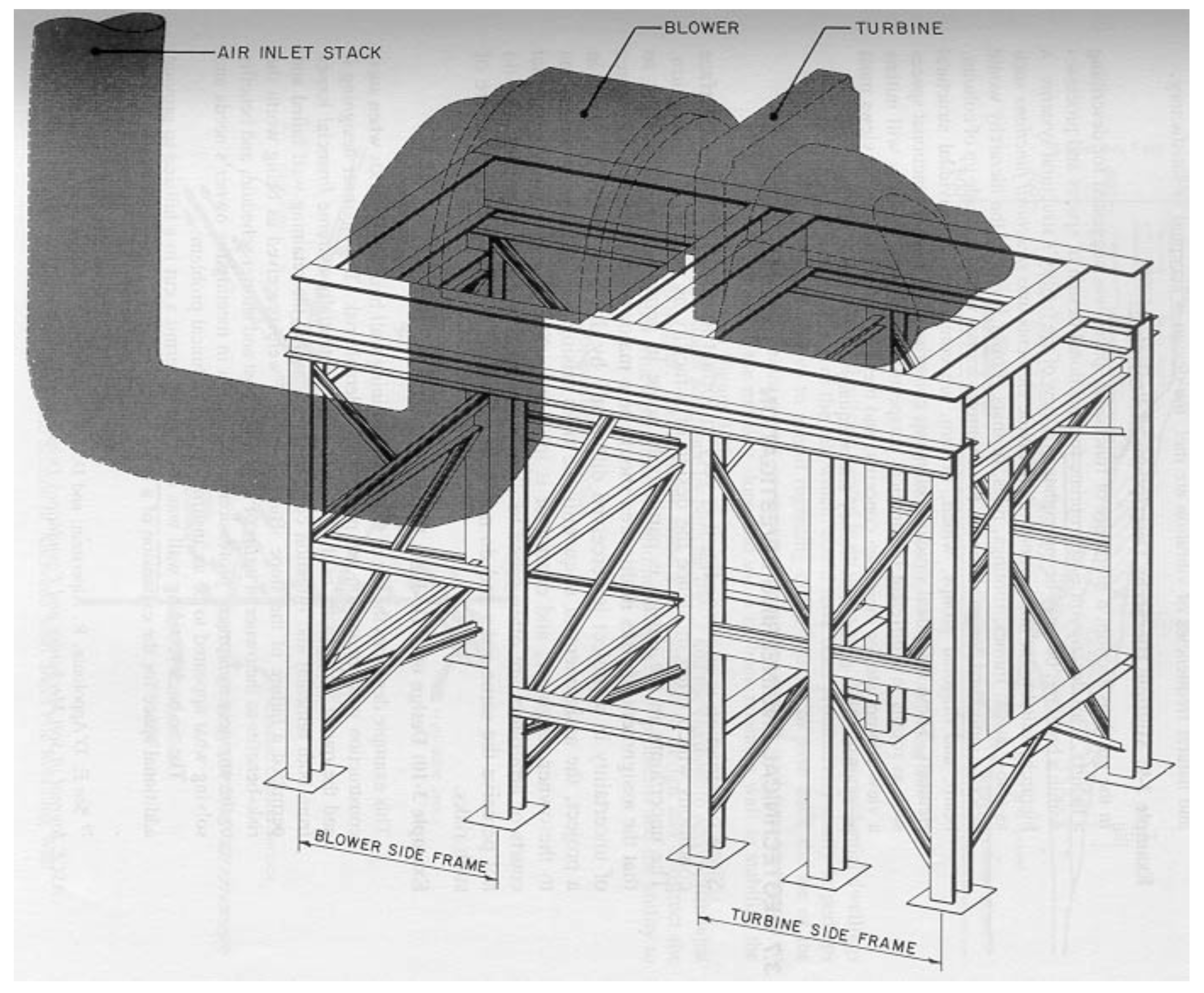
Figure 3-8: Steel Frame Supporting a Turbo-Blower
Example 3-9: Multiple hierarchy descriptions of projects
In the previous section, a hierarchy of functional spaces was suggested for describing a facility. This description is appropriate for functional design of spaces and processes within a building, but it may be inadequate as a view of the facility’s structural systems. A hierarchy suitable for this purpose might divide elements into structural functions such as slabs, walls, frames, footings, piles or mats. Lower levels of the hierarchy would describe individual design elements. For example, frames would be made up of column, beam and diagonal groups which, in turn, are composed of individual structural elements. These individual structural elements comprise the limits on functional spaces such as rooms in a different hierarchical perspective. Designers typically will initiate a view appropriate for their own concerns, and these different hierarchical views must be synthesized to insure consistency and adequacy of the overall design.
3.7 Geotechnical Engineering Investigation
Since construction is site specific, it is very important to investigate the subsurface conditions which often influence the design of a facility as well as its foundation. The uncertainty in the design is particularly acute in geotechnical engineering so that the assignment of risks in this area should be a major concern. Since the degree of uncertainty in a project is perceived differently by different parties involved in a project, the assignment of unquantifiable risks arising from numerous unknowns to the owner, engineer and contractor is inherently difficult. It is no wonder that courts or arbitrators are often asked to distribute equitably a risk to parties who do not perceive the same risks and do not want to assume a disproportionate share of such risks.
Example 3-10: Design of a tie-back retaining wall [15]
This example describes the use of a tie-back retaining wall built in the 1960’s when such construction was uncommon and posed a considerable risk. The engineer designing it and the owner were aware of the risk because of potentially extreme financial losses from both remedial and litigation costs in the event that the retaining wall failed and permitted a failure of the slope. But the benefits were perceived as being worth the risk–benefits to the owner in terms of both lower cost and shorter schedule, and benefits to the engineer in terms of professional satisfaction in meeting the owner’s needs and solving what appeared to be an insurmountable technical problem.
The tie-back retaining wall was designed to permit a cut in a hillside to provide additional space for the expansion of a steel-making facility. Figure 3-9 shows a cross section of the original hillside located in an urban area. Numerous residential dwellings were located on top of the hill which would have been prohibitively costly or perhaps impossible to remove to permit regrading of the hillside to push back the toe of the slope. The only realistic way of accomplishing the desired goal was to attempt to remove the toe of the existing slope and use a tie-back retaining wall to stabilize the slope as shown in Figure 3-10.
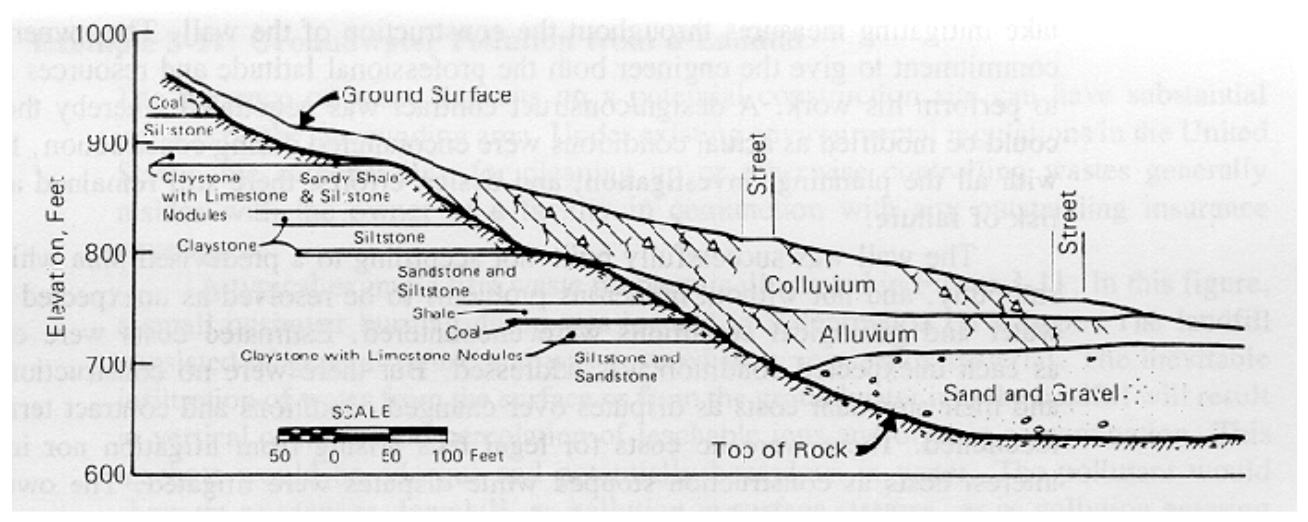
Figure 3-9: Typical Cross Section of Hillside Adjoining Site
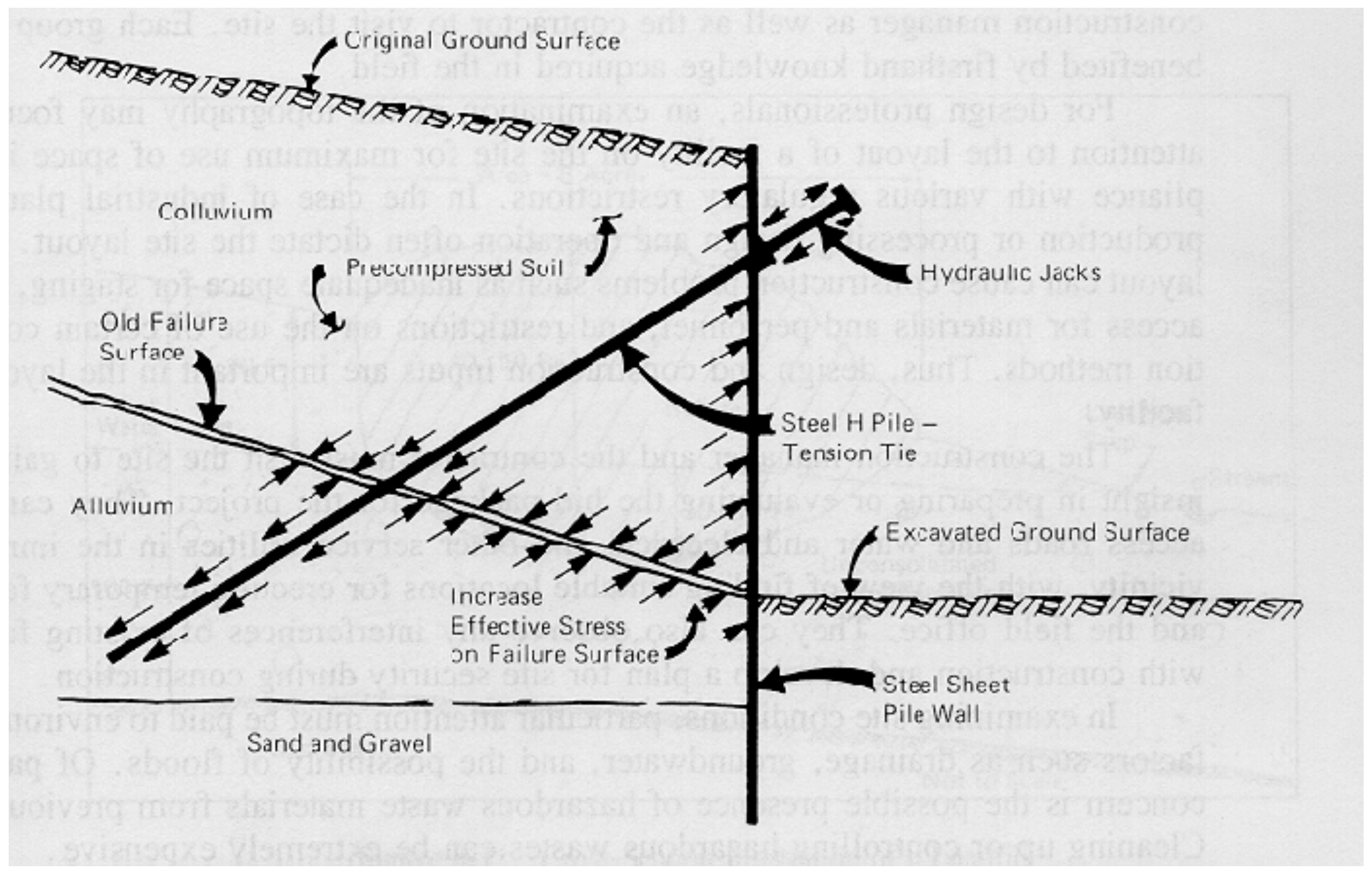
Figure 3-10: Schematic Section of Anchored Steel Sheet Pile Retaining Wall
A commitment was made by both the owner and the engineer to accomplish what was a common goal. The engineer made a commitment to design and construct the wall in a manner which permitted a real-time evaluation of problems and the ability to take mitigating measures throughout the construction of the wall. The owner made a commitment to give the engineer both the professional latitude and resources required to perform his work. A design-construct contract was negotiated whereby the design could be modified as actual conditions were encountered during construction. But even with all of the planning, investigation and design efforts, there still remained a sizable risk of failure.
The wall was successfully built–not according to a pre-devised plan which went smoothly, and not without numerous problems to be resolved as unexpected groundwater and geological conditions were encountered. Estimated costs were exceeded as each unexpected condition was addressed. But there were no construction delays and their attendant costs as disputes over changed conditions and contract terms were reconciled. There were no costs for legal fees arising from litigation nor increased interest costs as construction stopped while disputes were litigated. The owner paid more than was estimated, but not more than was necessary and not as much as if he had to acquire the property at the top of the hill to regrade the slope. In addition, the owner was able to attain the desired facility expansion in far less time than by any other method.
As a result of the success of this experience and others, the use of tie-back retaining walls has become a routine practice six decades later.
3.8 Construction Site Environment
While the general information about the construction site is usually available at the planning stage of a project, it is important for the design professionals and construction manager as well as the contractor to visit the site. Each group will be benefited by first-hand knowledge acquired in the field.
For design professionals, an examination of the topography may focus their attention to the layout of a facility on the site for maximum use of space in compliance with various regulatory restrictions. In the case of industrial plants, the production or processing design and operation often dictate the site layout. A poor layout can cause construction problems such as inadequate space for staging, limited access for materials and personnel, and restrictions on the use of certain construction methods. Thus, design and construction inputs are important in the layout of a facility.
The construction manager and the contractor must visit the site to gain some insight in preparing or evaluating the bid package for the project. They can verify access roads and water, electrical and other service utilities in the immediate vicinity, with the view of finding suitable locations for erecting temporary facilities and the field office. They can also observe any interferences of existing facilities with construction and develop a plan for site security during construction.
In examining site conditions, particular attention must be paid to environmental factors such as drainage, groundwater and the possibility of floods. Of particular concern is the possible presence of hazardous waste materials from previous uses. Cleaning up or controlling hazardous wastes can be extremely expensive.
Example 3-11: Groundwater Pollution from a Landfill [16]
The presence of waste deposits on a potential construction site can have substantial impacts on the surrounding area. Under existing environmental regulations in the United States, the responsibility for cleaning up or otherwise controlling wastes generally resides with the owner of a facility in conjunction with any outstanding insurance coverage.
A typical example of a waste problem is illustrated in Figure 3-11. In this figure, a small pushover burning dump was located in a depression on a slope. The landfill consisted of general refuse and was covered by a very sandy material. The inevitable infiltration of water from the surface or from the groundwater into the landfill will result in vertical or horizontal percolation of leachable ions and organic contamination. This leachate would be odorous and potentially hazardous in water. The pollutant would show up as seepage downhill, as pollution in surface streams, or as pollution entering the regional groundwater.
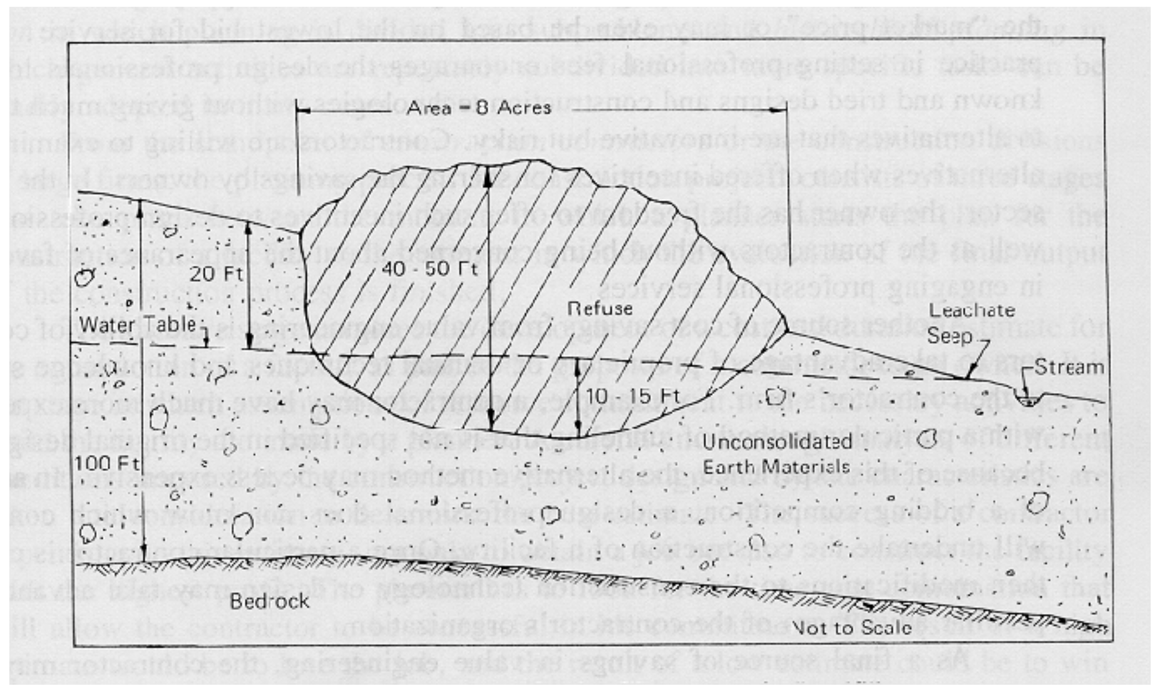
Figure 3-11: Cross-Section Illustration of a Landfill
Before new construction could proceed, this landfill site would have to be controlled or removed. Typical control methods might involve:
-
- Surface water control measures, such as contour grading or surface sealing.
- Passive groundwater control techniques such as underground barriers between the groundwater and the landfill.
- Plume management procedures such as pumping water from surrounding wells.
- Chemical immobilization techniques such as applying surface seals or chemical injections.
- Excavation and reburial of the landfill requiring the availability of an engineered and environmentally sound landfill.
The excavation and reburial of even a small landfill site can be very expensive. For example, the estimated reburial cost for a landfill like that shown in Figure 3-11 was in excess of $ 4 million in 1978.
3.9 Value Engineering
Value engineering may be broadly defined as an organized approach in identifying unnecessary costs in design and construction and in soliciting or proposing alternative design or construction technology to reduce costs without sacrificing quality or performance requirements. It usually involves the steps of gathering pertinent information, searching for creative ideas, evaluating the promising alternatives, and proposing a more cost-effective alternative. This approach is usually applied at the beginning of the construction phase of the project life cycle.
The use of value engineering in the public sector of construction has been fostered by legislation and government regulation, but the approach has not been widely adopted in the private sector of construction. One explanation may lie in the difference in practice of engineering design services in the public and private sectors. In the public sector, the fee for design services is tightly monitored against the “market price,” or may even be based on the lowest bid for service. Such a practice in setting professional fees encourages the design professionals to adopt known and tried designs and construction technologies without giving much thought to alternatives that are innovative but risky. Contractors are willing to examine such alternatives when offered incentives for sharing the savings by owners. In the private sector, the owner has the freedom to offer such incentives to design professionals as well as the contractors without being concerned about the appearance of favoritism in engaging professional services.
Another source of cost savings from value engineering is the ability of contractors to take advantage of proprietary or unusual techniques and knowledge specific to the contractor’s firm. For example, a contractor may have much more experience with a particular method of tunneling that is not specified in the original design and, because of this experience, the alternative method may be less expensive. In advance of a bidding competition, a design professional does not know which contractor will undertake the construction of a facility. Once a particular contractor is chosen, then modifications to the construction technology or design may take advantage of peculiar advantages of the contractor’s organization.
As a final source of savings in value engineering, the contractor may offer genuine new design or construction insights which have escaped the attention of the design professional even if the latter is not restrained by the fee structure to explore more alternatives. If the expertise of the contractor can be utilized, of course, the best time to employ it is during the planning and design phase of the project life cycle. That is why professional construction management or integrated design/construction are often preferred by private owners.
3.10 Construction Planning
The development of a construction plan is very much analogous to the development of a good facility design. The planner must weigh the costs and reliability of different options while at the same time insuring technical feasibility. Construction planning is more difficult in some ways since the building process is dynamic as the site and the physical facility change over time as construction proceeds. On the other hand, construction operations tend to be fairly standard from one project to another, whereas structural or foundation details might differ considerably from one facility to another.
Forming a good construction plan is an exceptionally challenging problem. There are numerous possible plans available for any given project. While past experience is a good guide to construction planning, each project is likely to have special problems or opportunities that may require considerable ingenuity and creativity to overcome or exploit. Unfortunately, it is quite difficult to provide direct guidance concerning general procedures or strategies to form good plans in all circumstances. There are some recommendations or issues that can be addressed to describe the characteristics of good plans, but this does not necessarily tell a planner how to discover a good plan. However, as in the design process, strategies of decomposition in which planning is divided into subproblems and hierarchical planning in which general activities are repeatably subdivided into more specific tasks can be readily adopted in many cases.
From the standpoint of construction contractors or the construction divisions of large firms, the planning process for construction projects consists of three stages that take place between the moment in which a planner starts the plan for the construction of a facility to the moment in which the evaluation of the final output of the construction process is finished.
The estimate stage involves the development of a cost and duration estimate for the construction of a facility as part of the proposal of a contractor to an owner. It is the stage in which assumptions of resource commitment to the necessary activities to build the facility are made by a planner. A careful and thorough analysis of different conditions imposed by the construction project design and by site characteristics are taken into consideration to determine the best estimate. The success of a contractor depends upon this estimate, not only to obtain a job but also to construct the facility with the highest profit. The planner has to look for the time-cost combination that will allow the contractor to be successful in his commitment. The result of a high estimate would be to lose the job, and the result of a low estimate could be to win the job, but to lose money in the construction process. When changes are done, they should improve the estimate, taking into account not only present effects, but also future outcomes of succeeding activities. It is very seldom the case in which the output of the construction process exactly echoes the estimate offered to the owner.
In the monitoring and control stage of the construction process, the construction manager has to keep constant track of both activities’ durations and ongoing costs. It is misleading to think that if the construction of the facility is on schedule or ahead of schedule, the cost will also be on the estimate or below the estimate, especially if several changes are made. Constant evaluation is necessary until the construction of the facility is complete. When work is finished in the construction process, and information about it is provided to the planner, the third stage of the planning process can begin.
The evaluation stage is the one in which results of the construction process are matched against the estimate. A planner deals with this uncertainty during the estimate stage. Only when the outcome of the construction process is known is he/she able to evaluate the validity of the estimate. It is in this last stage of the planning process that he or she determines if the assumptions were correct. If they were not or if new constraints emerge, he/she should introduce corresponding adjustments in future planning.
3.11 Industrialized Construction and Pre-fabrication
Another approach to construction innovation is to apply the principles and organizational solutions adopted for manufacturing. Industrialized construction and pre-fabrication involve transferring a significant portion of construction operations from the construction site to more or less remote sites where individual components of buildings and structures are produced. Elements of facilities could be prefabricated off the erection site and assembled by cranes and other lifting machinery.
There are a wide variety and degrees of introducing greater industrialization to the construction process. Many components of constructed facilities have always been manufactured, such as air conditioning units. Lumber, piping and other individual components are manufactured to standard sizes. Even temporary items such as forms for concrete can be assembled off-site and transported for use. Reinforcing bars for concrete can also be pre-cut and shaped to the desired configuration in a manufacturing plant or in an automated plant located proximate to a construction site.
A major problem in extending the use of pre-fabricated units is the lack of standardization for systems and building regulations.[17] While designers have long adopted standard sizes for individual components in designs, the adoption of standardized sub-assemblies is rarer. Without standardization, the achievement of a large market and scale economies of production in manufacturing may be impossible. An innovative and more thorough industrialization of the entire building process may be a primary source of construction cost savings in the future.
However, as noted previously in section 3.3 the situation has been changing, and this industrialization movement has been making substantial recent progress recently (2020 onward). Exponential modularization industry growth of 5-8 % compound per year has been experienced from around 2015. The McKinsey & Company report from 2019 on this trend is enlightening.
Example 3-12: Planning of pre-fabrication
When might prefabricated components be used in preference to components assembled on a construction site? A straightforward answer is to use prefabricated components whenever their cost, including transportation, is less than the cost of assembly on site. As an example, forms for concrete panels might be transported to a construction site with reinforcing bars already built in, necessary coatings applied to the forms, and even special features such as electrical conduit already installed in the form. In some cases, it might be less expensive to pre-fabricate and transport the entire concrete panel to a manufacturing site. In contrast, traditional construction practice would be to assemble all the different features of the panel on-site. The relevant costs of these alternatives could be assessed during construction planning to determine the lowest cost alternative. Most estimating departments have recent values for these alternatives in different regions, and it is common in 2023 to default to prefab for much of the project. For example, ICFs (insulated concrete forms) have become extremely common in some areas.
In addition to the consideration of direct costs, a construction planner should also consider some other aspects of this technology choice. First, the planner must ensure that prefabricated components will satisfy the relevant building codes and regulations (note that structural design codes for ICFs have maximum number of floors depending on jurisdiction – typically 8 to 12). Second, the relative quality of traditional versus prefabricated components as experienced in the final facility should be considered. Finally, the availability of components at the required time during the construction process should also be considered.
Example 3-13: Impacts of building codes[18]
Building codes originated as a part of the building regulatory process for the safety and general welfare of the public. The source of all authority to enact building codes is based on the police power of the state which may be delegated by the state legislature to local government units. Consequently, in the US about 8,000 localities having their own building codes, either by following a national model code or developing a local code. Consequently, national home builders must hire code consultants, solely for the purpose of adapting their products to different localities. Some progress in online automated code checkers using BIMs as input is being made however. The lack of uniformity of building codes may be attributed to a variety of reasons:
-
- Neighboring municipalities may adopt different national models as the basis for local regulation.
- Periodic revisions of national codes may not be adopted by local authorities before the lapse of several years.
- Municipalities may explicitly decline to adopt specific provisions of national model codes or may use their own variants of key provisions.
- Local authorities may differ in interpretation of the same language in national model codes.
The lack of uniformity in building codes has serious impact on design and construction as well as the regulatory process for buildings. Among the significant factors are:
-
- Delay in the diffusion of new building innovations which may take a long time to find their ways to be incorporated in building codes.
- Discouragement to new production organizations, such as industrialized construction and prefabrication.
- Duplication of administrative cost of public agencies and compliance cost incurred by private firms.
3.12 Computer-Aided Engineering
New capabilities, systems and application programs are continuously being adopted. These are motivated in part by the relentless improvement in computing power, the internet, cloud computing, AI, MR (mixed reality), BIM, BIM plug-ins, structural and other systems design software, gaming engines, physics engines, and corresponding extraordinary declines in cost. Computers are also being applied more and more extensively to non-analytical and non-numerical tasks. For example, AI-based specification writing assistants are used to rapidly assemble sets of standard specifications or to insert special clauses in the documentation of facility designs. Computerized transfer of information via automated workflow systems provides a means to avoid laborious, and error-prone transcription of project information. Computer and AI assistants will soon become ubiquitous in virtually all project management organizations. The impact of information technology and AI will be addressed more thoroughly in a later chapter.
3.13 Pre-Project Planning
Even before design and construction processes begin, there is a stage of “pre-project planning” that can be critical for project success. In this process, the project scope is established. Since construction and design professionals are often not involved in this project scope stage, the terminology of describing this as a “pre-project” process has arisen. From the owner’s perspective, defining the project scope is just another phase in the process of acquiring a constructed facility.
The definition of a project scope typically involves developing project alternatives at a conceptual level, analyzing project risks and economic payoff, developing a financial plan, making a decision to proceed (or not), and deciding upon the project organization and control plan. The next few chapters will examine these different problems at some length.
The danger of poor project definition comes from escalating costs (as new items are added) or, in the extreme, project failure. A good definition of scope allows all the parties in the project to understand what is needed and to work towards meeting those needs.
Example 3-14: The Project Definition Rating Index (PDRI) for Building Projects
The Construction Industry Institute has developed rating indexes for different types of projects to assess the adequacy of project scope definitions.[20] These are intended to reflect best practices in the building industry and provides a checklist for recommended activities and milestones to define a project scope. The rating index is a weighted sum of scores received for a variety of items on the scope definition checklist. Each item in the checklist is rated as “not applicable” (0), “complete definition” (1), “minor deficiencies” (2), “some deficiencies” (3), “major deficiencies” (4) or “incomplete or poor definition” (5). Lower scores in these categories are preferable. Some items in the checklist include:
-
- Business Strategy for building use, justification, plan, economic analysis, facility requirements, expansion/alteration consideration, site selection issues and project objectives.
- Owner Philosophy with regard to reliability, maintenance, operation and design.
- Project Requirements for value engineering, design, existing facility, scope of work review, schedule and budget.
- Site Information including applicable regulatory reporting and permits requirements.
- Building Programming including room by room definitions for use, finishes, interior requirements and HVAC (heating, ventilating and air conditioning).
- Design Parameters including all components and a constructability analysis.
- Equipment including inventory, locations and utility requirements.
3.14 References
- Au, T. and P. Christiano, Structural Analysis, Prentice-Hall, Inc., Englewood Cliffs, NJ, 1987.
- Building Research Advisory Board, Exploratory Study on Responsibility, Liability and Accountability for Risks in Construction, National Academy of Sciences, Washington, D.C., 1978.
- Drucker, P.F., Innovation and Entrepreneurship: Practice and Principles, Harper and Row, New York, 1985.
- Gaylord, E., and C. Gaylord (Editors), Structural Engineering Handbook, McGraw-Hill Book Co., New York, 1979.
- Levitt, R.E., R.D. Logcher and N.H. Quaddumi, “Impact of Owner-Engineer Risk Sharing on Design Conservatism,” ASCE Journal of Professional Issues in Engineering, Vol. 110, 1984, pp. 157-167.
- Simon, H.A., The Science of the Artificial, Second Edition, MIT Press, Cambridge, MA, 1981.
- Tatum, C.B., “Innovation on the Construction Project: A Process View,” Project Management Journal, Vol. 18, No. 5, 1987, pp. 57-67.
- Pre-Project Planning Research Team, Pre-Project Planning Handbook Construction Industry Institute, Publication 39-2, April 1995.
3.15 Footnotes
- See “ASCE Unveils Quality Manual”, ENR, November 5, 1987, p. 14) Back
- See V. Fairweather, “Milan’s Model Metro”, Civil Engineering, December 1987, pp. 40-43.Back
- See T.Y. Lin and B.G. Gerwick, Jr. “Design of Long Span Concrete Bridges with Special References to Prestressing, Precasting, Structural Behavior and Economics,” ACI Publication SP-23, First International Symposium, 1969, pp. 693-704 Back
- See Linnhoff, B., D.W. Townsend, D. Boland, G.F. Hewitt, B.E.A. Thomas, A.R. Guy, and R.H. Marsland, User Guide on Process Integration for the Efficient Use of Energy, Institution of Chemical Engineers, Rugby, Warks., England, 1982. Back
- “More Construction for the Money,” Summary Report of the Construction Industry Cost Effectiveness Project, The Business Roundtable, New York, 1983, pg. 30. Back
- See “The Quiet Revolution in Skyscraper Design, ” Civil Engineering, May 1983, pp. 54-59. Back
- See J. Landis, “Why Homebuilders Don’t Innovate,” Built Environment, Vol. 8, No. 1, 1982, pp. 46-53. Back
- See P.J. Cassimates, Economics of the Construction Industry, National Industry Conference Board (SBE No. 111), 1969. Back
- See F. Moavenzadeh, “Construction’s High Technology Revolution,” Technology Review, October, 1985, pp. 32-39. Back
- For more information on Green Buildings see the LEED website: http://www.usgbc.org/LEED/LEED_main.asp Back
- See R.W. Jensen and C.C. Tonies (Editors), Software Engineering, Prentice-Hall, Inc., Englewood Cliffs, NJ, 1979, p. 22. Back
- See S.J. Fenves, “Computer Applications,” in Structural Engineering Handbook, (Gaylord, E. and C. Gaylord, Editors), McGraw-Hill Book Co., New York, NY, 1979. Back
- See T. Au, E.W. Parti and A.K.C. Wong, “Computer Applications for Health Care Facility Design,” Computers in Biology and Medicine, Vol. 1, No. 4, 1971, pp. 299-316. Back
- The authors are indebted to E. D’Appolonia for suggesting this example. Back
- See E. D’Appolonia, R. Alperstein and D.J. D’Appolonia, “Behavior of Colluvial Slope”, ASCE Journal of Soil Mechanics and Foundations Division, Vol. 93, No. SM4, 1967, pp. 447-473. Back
- The material in this example is adapted from A.L. Tolman, A. P. Ballestero, W.W. Beck, G.H. Emrich, “Guidance Manual for Minimizing Pollution from Waste Disposal Sites,” Report to the Municipal Environmental Research Laboratory, U.S. Environmental Protection Agency, EPA-600/2-78-142, August 1978. Back
- For discussions of industrialized building, see Bender, Richard, A Crack in the Rear View Mirror – A View of Industrialized Building, Von Nostrand Reinhold Co., 1983; Nutt-Powell, Thomas, E., Manufactured Homes: Making Sense of a Housing Opportunity, Auburn House, 1982; or Warzawski, A., M. Avraham, and D. Carmel, “Utilization of Precast Concrete Elements in Building,” ASCE Journal of Construction Engineering and Management, Vol. 110, No. CO4, 1984, pp. 476-485. Back
- See C.G. Field and S.R. Rivkin, The Building Code Burden, Lexington Books, D.C. Heath and Co., Lexington, MA, 1975. Back
- See Rehak, Daniel R. and L.A. Lopez, Computer Aided Engineering Problems and Prospects, Dept. of Civil Engineering, University of Illinois, 1981. Back
- See PDRI for Building Projects Research Team, PDRI: Project Definition Rating Index for Building Projects, Construction Industry Institute, Resource 155-2, July 1999.Back
