EXPERIMENT 4: MEMBRANE FILTRATION
Introduction
While conventional plate and frame type filtration units can separate undissolved solids from liquids, modern cross-flow or tangential-flow systems can actually separate dissolved solids such as salts and sugars from liquids. This type of filtration is referred to as membrane filtration as the medium that separates the liquid from the dissolved solid is a thin membrane.
In membrane filtration, the suspension is passed over the membrane not at right angles but rather parallel or at a slight angle so that particles that are too large to pass through the membrane are carried away with the suspension, rather than building up and fouling the membrane surface. The portion of the suspension that passes through the membrane is called the permeate while the portion that does not is called the retentate.
Membrane filtration units are classified by the size of molecules that pass through the membrane itself (GEA Filtration, Membrane Filtration, https://www.gea.com/en/binaries/membrane-filtration-ultrafiltration-nanofiltration-microfiltration-reverse-osmosis-gea_tcm11-34841.pdf):
- Microfiltration – a low pressure cross-flow filtration process for separating larger colloidal and suspended particles, 0.05 – 10 microns in diameter; used in fermentation, broth clarification and biomass clarification and recovery.
- Ultrafiltration – a selective process using pressures up to 145 psi to fractionate milk, whey and other proteins. It concentrates suspended solids and solutes of molecular weight greater than 1,000 while the permeate carries solutes with molecular weight less than 1,000.
- Nanofiltration – can perform separation processes such as demineralization, colour removal and suspended solids removal. The permeate contains monovalent ions and low molecular weight organic solutions like alcohol.
- Reverse Osmosis – a high pressure process (400- 600 psi), high efficient technique used for dewatering process streams, concentrating/separating low molecular weight substances, cleaning wastewater and desalinating seawater.
Membranes are also classified by their configuration. The most common types are tubular, hollow fiber and spiral bound membranes. Suez is a manufacturer of these filtration systems and their “water handbook” website, https://www.suezwaterhandbook.com/, provides much information including photos and schematic diagrams.
Tubular membranes operate in tangential, or cross-flow, design where process fluid is pumped along the membrane surface in a sweeping type action. The membrane is cast on the inside surface of a porous tube. The feed solution is pumped through the center of the tube at velocities as high as 20 ft/sec. These cross-flow velocities minimize the formation of a concentration polarization layer on the membrane surface, promoting high and stable flux and easy cleaning, especially when the objective is to achieve high suspended solids in the microfiltration, ultrafiltration or nanofiltration concentrate. Permeate is driven through the membrane to be directed out of the system or back into the process depending on the application. A tubular membrane is shown in Figure 1.
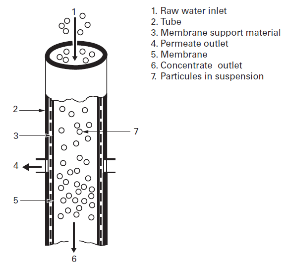
Figure 1: Tubular membrane design, from Suez, degremont® Water Handbook, 2019, https://www.suezwaterhandbook.com/processes-and-technologies/separation-by-membranes/available-modules-their-geometry/tubular-modules
The hollow fiber geometry allows a high membrane surface area to be contained in a compact module. This means large volumes can be filtered, while utilizing minimal space, with low power consumption. Hollow fiber membranes can be designed for circulation, dead-end, and single-pass operations. The hollow fiber geometry is shown in Figure 2.
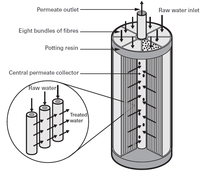
Figure 2: Hollow fiber membrane design, from Suez, degremont® Water Handbook, 2019, https://www.suezwaterhandbook.com/processes-and-technologies/separation-by-membranes/available-modules-their-geometry/hollow-fibre-modules
Spiral membranes span the full spectrum of membrane filtration from microfiltration down to reverse osmosis. A spiral membrane is shown in Figure 3. A flexible porous sheet (collector) (11) is inserted between two flat membranes (10). Three sides of this sandwich are sealed (12). The open side is welded to a cylindrical collector tube (3) on either side of a generatrix through which holes have been drilled. Several such sandwiches are installed, separated from each other by a spacer (flexible plastic screen) (9). The fluid to be treated circulates in the spacer (9), parallel to the collector tube; the collector (11) discharges the permeate to the axial collector (3).
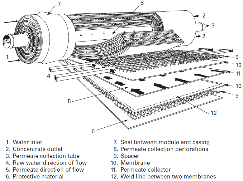
Figure 3: Spiral wound membrane design, from Suez, degremont® Water Handbook, 2019,https://www.suezwaterhandbook.com/processes-and-technologies/separation-by-membranes/available-modules-their-geometry/spiral-wound-modules
Spiral wound elements are generally the more economical to operate. They are compact as high membrane packing density results in more efficient utilization of floor space. They are are also energy efficient having lower power consumption compared to other membrane configurations. However, they are susceptible to fouling because of the tight spacing and, to avoid regular fouling, require water pre-treatment. Almost all desalination modules nowadays are designed with spiral wound membranes.
The system in E030 is a very simplified tubular membrane filtration unit. A Figure of the unit with major components highlighted is provided in Figure 4.
Figure 4: Membrane filtration unit with major components highlighted.
The solution that needs to be filtered is continuously recycled through the two tubular membrane units. Retentate is returned to the tank holding the solution while permeate is collected on the side of the system. A centrifugal pump is used for pushing the liquid through the membrane units while a valve at the end of the piping can be used to adjust the pressure in the membranes during the process.
Purpose
The purpose of this experiment is:
- To determine the effect of pressure on filtration rates
- To determine the type of filtration that takes place
Procedure
- Fill the tank with 40 L of tap water (up to the dotted line on the side of the tank).
- Ensure that the permeate outflow is collected to one or two separate containers.
- Turn on the pump by plugging it on the outlet behind the unit. You might need to prime the pump in order for it to circulate liquid through the membrane units.
Permeate flow rate
- Use the valve at end of the fluid line (after the membrane units) to set the pressure in the line (also called back pressure) to 5 psi.
- Collect the permeate for a set amount of time (3 to 5 minutes) to determine the volumetric flow rate of permeate.
- Repeat steps 1 to 3 for line back pressures of 10 and 20 psi.
Filtration Characteristics
Determine whether the system is reverse osmosis, nanofiltration, ultrafiltration or microfiltration. This can by done by processing the following solutions and determining which species pass through the membrane:
- 0.1 % salt solution – test with silver nitrate
- 0.15% starch solution – test with iodized potassium iodide solution
- 0.05 % protein solution – test with biuret solution
The process is as follows:
- Put enough salt into the tank to make a 0.1% (1 g salt/liter) salt solution. Stir the water to dissolve the salt.
- Measure the permeate flow rate at back pressures of 5, 10, and 20 psi
- Keep the permeate from the 20 psi run and test if salt went through the membrane (test with silver nitrate). Refer to the Appendix at the end of this experimental procedure to see the proper method of testing.
- Add enough starch into the tank to make a 0.15% (1.5 g starch/liter) starch solution. Stir the water to dissolve the starch.
- Measure the permeate flow rate at back pressures of 5, 10, and 20 psi
- Keep the permeate from the 20 psi run and test if starch went through the membrane (test with potassium iodide). Refer to the Appendix at the end of this experimental procedure to see the proper method of testing.
- Add enough protein (egg albumin) into the tank to make a 0.05% (0.5 g protein/liter) protein solution. Stir the water to dissolve the protein.
- Measure the permeate flow rate at back pressures of 5, 10, and 20 psi
- Keep the permeate from the 20 psi run and test if protein went through the membrane (test with biuret solution).
Clean-up
At the end of the lab, empty the tank using the drain line and the small container or bucket. Rinse the tank. Then, fill it with tap water and flush the system by running water through it for 5 minutes. Empty the tank at the end.
Report
- Generate one plot of permeate flow rate vs pressure. The plot must contain four data sets: one from the initial flow rate measurement and one from each of the trials with the added substances in the water.
- Discuss the type of filtration that takes place and indicate how you determined this.
Appendix
To determine if a species passed through the membrane you can do the following:
- Find three similar test tubes or small beakers. It is essential that they are the same, as your judgement will be based on colour and the colour intensity depends on the optical length through the container.
- Half-way fill the first tube with distilled water, the second with a sample from the tank and the third with a sample from the permeate.
- Add a few drops of the appropriate testing solution on each of the tubes and properly mix.
- Compare the colours of the three tubes.
- If the colour of the permeate tube matches that of the tank tube, then the species went through the membrane. If not, then the species did not go through the membrane. The distilled water tube is used more a “buffer” for visualizing the colour of the testing solution.