EXPERIMENT 8: PLATE HEAT EXCHANGER
Introduction:
For many decades, the tube-and-shell heat exchanger has been the workhorse of the chemical process industry, but the high heat transfer rates, and resulting compactness, of plate heat exchangers have made them the popular modern choice, especially for liquid-liquid systems. The fluids flow in “S” shaped patterns along a thin steel plate, with the other fluid on the other side of the plate, usually in counter-current flow.
A plate heat exchanger apparatus consists of a pack of plates with sealing gaskets held together in a frame between a fixed end plate and a moving end plate. Hot and cold fluids flow between channels on alternate sides of plates to promote heat transfer. As in any heat exchanger, the two fluids never mix but only exchange energy through the metal plate that separates them. In a co-current heat exchanger, hot and cold fluids flow in the same direction on either side of a plate. In a counter-current heat exchanger, hot and cold fluids flow in opposite directions.
A very good visualization of plate-and-frame heat exchangers, from Sondex A/S, can be is shown below (Sondex A/S, (2014, Feb 26), “Sondex Plate Heat Exchangers – Working Principles”, https://www.youtube.com/watch?v=Jv5p7o-7Pms):
There is also a very good, short, discussion, including typical uses, advantage and disadvantage, within the Visual Encyclopedia of Chemical Engineering from the University of Michigan: Here. In there you can also get a feeling of the size of industrial-scale plate-and-frame exchangers

Figure 1: Plate and Frame Heat Exchanger, Visual Encyclopedia of Chemical Engineering: Heat Exchangers (n.d.), http://encyclopedia.che.engin.umich.edu/Pages/EnergyTransfer/HeatExchangers/HeatExchangers.html
The fluid to be heated or cooled is referred to as the process fluid, while the fluid which does the heating or cooling is called the service fluid. In a lab situation, the designations of process & service are somewhat arbitrary, but we usually treat the hot water as the process stream and the cold water as the service stream.
The heat gained by the cold water is:
(1) 
While the heat given up by the hot water is:
(2) 
Where
 |
mass flow rate, kg/s |
 |
mean specific heat , J/(kg °C) |
| T | inlet or outlet temperature (°C) |
| q | heat flow (Watt or J/s) |
Note that in the two equations provided above, the temperature difference for qc and qh is different (outlet – inlet) versus (inlet – outlet) to ensure that the calculated heat rate q is positive. In an ideal heat exchanger where no heat is lost to the surrounding, the amount of energy the cold liquid picks-up is the same as the amount on energy that the hot liquid loses:
(3) 
The driving force for heat transfer is the temperature difference, ΔT, between the hot water and the cold water. Because the temperature of the hot and cold streams changes throughout the experiment, the ΔT used in calculating the overall heat transfer coefficient is an average value between the maximum and minimum temperature different between the two fluids. In heat exchanger calculations, the ΔT used is the system’s “logarithmic mean temperature difference” (LMTD or ΔTlm):
(4) 
The terms  and
and  are used in the equation above because which temperatures of the two fluids are used depends on the whether the heat exchanger operates in parallel or counter flow. If the exchanger operates in parallel flow, one side of the exchanger has both the liquid inlets and the other side has both the liquid outlets. If the exchanger operates in counter flow, there is one inlet and one outlet at each side of the exchanger.
The plate-and-frame exchanger in the lab is counter flow, so:
(5) 
The Logarithmic Mean Temperature Difference (LMTD) can be used to calculate the heat transfer between the two fluids in the heat exchanger, provided the device’s characteristics are known:
(6) 
where
| U | Overall Heat Transfer Coefficient, W/(m2 °C) |
| A | Area available for heat transfer, m2 |
The area available for heat transfer is for a plate-and-frame heat exchanger is just the number of plates multiplied by the area of each plate. (for the lab heat-exchanger, there are 10 plates, each 6 inches by 16 inches). The overall heat transfer coefficient can be calculated using heat-transfer principles and the device’s design, which we do not cover in this lab. It can also be calculated by combining equations (1) or (2) and (6).
(7) 
The overall heat transfer coefficient is a characteristic of the heat exchanger and will remain constant as the inlet temperatures of the process and service fluids change (it depends, though, on their flowrates). Hence, once calculated, it can be used for future predictions on the amount of heat that can be transferred between the two fluids on the device.
The plate-and-frame heat exchanger in E030, shown in Figure 2, is a pilot-scale one with only 10 plates, each 6 inches by 16 inches. It is supplied with cold water and hot water from the facilities’ supply to the lab and is set-up for counter-flow of the two liquids. The systems is equipped with:
- Temperature sensors and transmitters for
- Cold water inlet temperature, in °C
- Cold water outlet temperature, in °C
- Hot water inlet temperature, in °C
- Hot water outlet temperature, in °C
- Flow sensors and transmitters for:
- Cold water flow, in US Gallons per minute (USGPM)
- Hot water flow, in US Gallons per minute (USGPM)
- Control valves for independently adjusting the cold water flow and the hot water flow. Note that both control valves are placed at the outlets of the fluid flow

Figure 2: Plate-and-Frame Heat Exchanger in E030
Figure 3 indicates the position of all the system’s instrumentation
Figure 3: Location of instrumentation of Plate-and-Frame Heat Exchanger in E030
The system has been automated and its main functions can be operated through a computer. Figure 4 shows the HMI (Human-Machine-Interface) and Figure 5 outlines the main data displayed on the HMI and how the user can interact with the system.
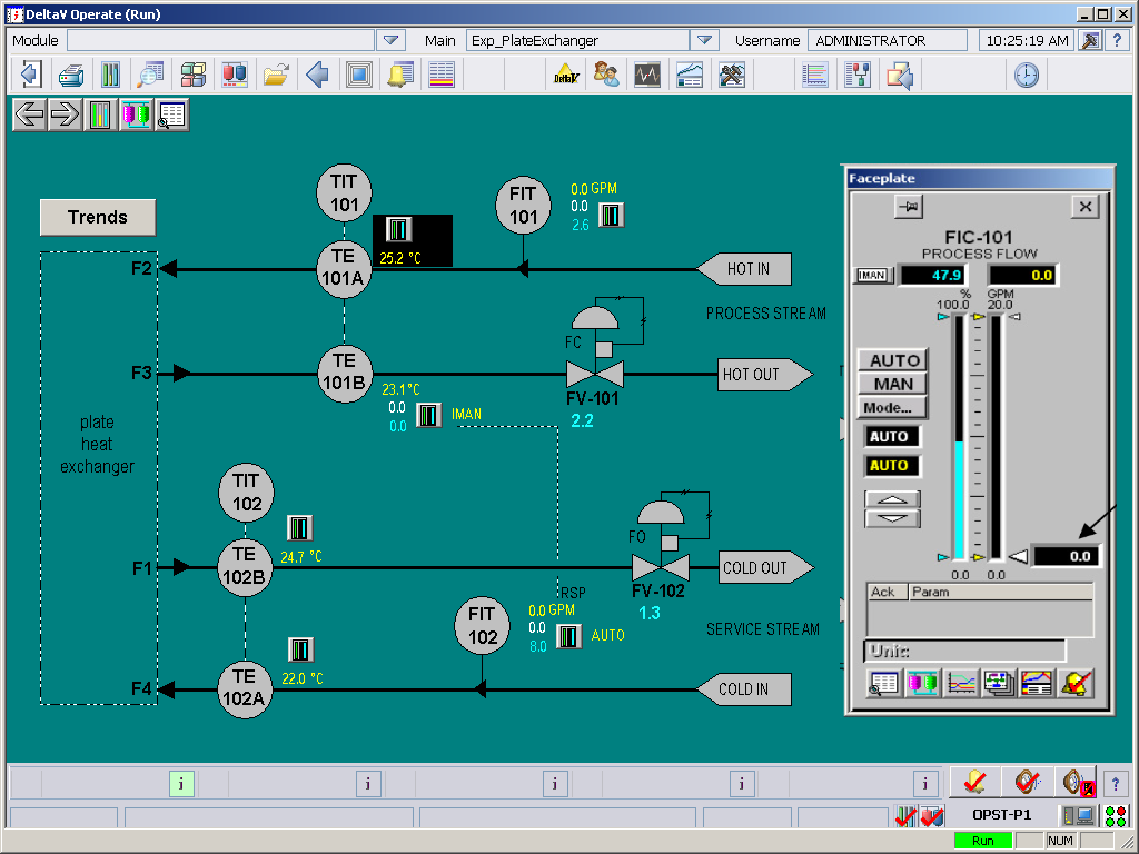
Figure 4: Plate-and-Frame Heat Exchanger HMI
Figure 5: Main functions of the Plate-and-Frame Heat Exchanger HMI
As noted in the Figure above, the HMI displays all inlet and outlet temperatures and the fluid flow rates. The flow rates are set through a control loop. The user inputs a set point through the faceplate, the actual flow rate is read using the flowmeter and then the control valve is opened or closed to adjust to the set point flow rate. This control loop is always active, provided the controller is set to AUTO. This helps in accommodating any flow variations in the building’s water supply and maintain a constant flow rate.
Purpose
The purpose of this experiment is:
- To find the heat flux and heat transfer coefficients at various service and process water flow rates.
- To determine the heat conserved, that is, the difference between the heat the hot water gives up and what the cold water receives.
Procedure:
- Completely open the hot and cold water valves near the sink.
- On the computer screen, set the hot water and cold water flow to a “high” rate (near 9 USGPM). This is done by calling up the faceplate for the hot and cold water flows (see Figure 5) and dragging the set-point value (white arrow) upward. Alternatively, the flow rate can be typed into the input box to a fixed setting. Allow the water to run for about 5 minutes, to reach stable temperatures.
Note what is the maximum flow rate that can be achieved for the cold and for the hot water. It that flow rate is less than 9 USGPM, this will be your upper limit for all the readings performed in the rest of the experiment, as it is limit by how much water flow is supplied to the building. - Set the cold water flow to about 2 USGPM and the hot water flow to about 2 USGPM.
- Record the flow rate and temperature of the two outlet streams and the two inlet steams when they are constant.
- While keeping the cold water flow rate constant, increase the hot water flow by 1 USGPM. Once the temperatures have stabilized, record the flows and temperature.
- Continue to increase the hot water flow until the maximum has been reached; then increase the cold water flow to 3 USGPM and repeat all the flows for the hot water.
- Continue the procedure until the maximum possible cold water flow has been reached. In the end, you must have created a table as shown in Table 1.
Table 1: Observations for Plate Heat Exchanger Runs
| Hot water flow, qh (USGPM) | Cold water flow, qc (USGPM) |
Th,in (ºC) | Th,out (ºC) | Tc,in (ºC) | Tc,out (ºC) |
| 2 | 2 | ||||
| 3 | 2 | ||||
| 4 | 2 | ||||
| 5 | 2 | ||||
| 6 | 2 | ||||
| 7 | 2 | ||||
| 8 | 2 | ||||
| 9 | 2 | ||||
| 2 | 3 | ||||
| 3 | 3 | ||||
| 4 | 3 | ||||
| 5 | 3 | ||||
| 6 | 3 | ||||
| 7 | 3 | ||||
| 8 | 3 | ||||
| 9 | 3 | ||||
| 2 | 4 | ||||
| Etc … | |||||
| 9 | 9 |
Report:
While performing the following calculations, please check Figure 7 at the end of this lab manual for a suggested table and samples of proper calculations.
First, the raw heat transfer data can be analyzed.
- For each single set of readings (i.e. every row on Table 1), calculate the following. Perform all calculations through a spreadsheet, but provide detailed written calculations for one row of your sheet.:
- The rate of energy lost from the hot liquid, qh in Watt
- The rate of energy gain from the cold liquid, qc in Watt
- The rate at which energy is lost from the system,

- The efficiency of the heat exchanger in transferring energy from the hot to the cold water. The efficiency can be defined as the ratio of energy picked-up by the cold fluid by the energy lost by the hot fluid
%efficiency =
- Plot the following:
- qh vs hot water flow rate. The graph must include multiple lines with each line corresponding to a different cold-water flow rate value, as shown in Figure 6.
- Energy lost,
 , vs. hot water flow rate. The graph must include multiple lines with each line corresponding to a different cold-water flow rate value.
 - Heat exchanger efficiency vs. hot water flow rate. The graph must include multiple lines with each line corresponding to a different cold-water flow rate value.
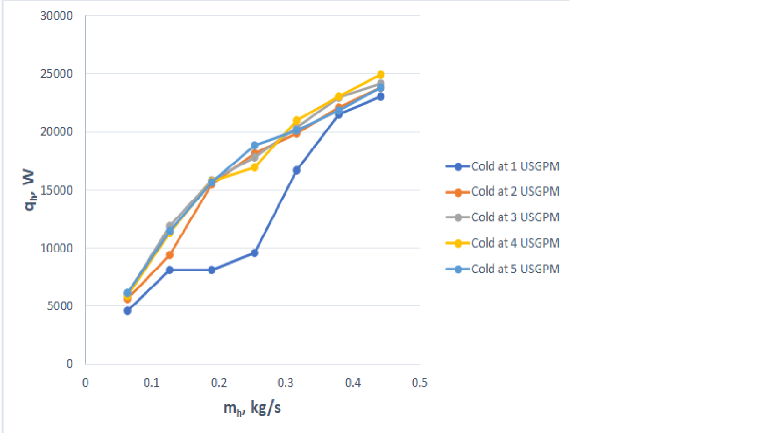 Figure 6: Plot of qh versus hot water flow rate for several cold water flow rates
- Comment on the following. Not only state the optimum condition, for each the questions below, but also discuss why, in your opinion, the optimum is at that condition:
- What conditions provide the maximum heat exchanger efficiency?
- When is the heat transfer rate between the two fluid maximized (that point might be different than the point of maximum efficiency)?
- When is the lost energy minimized?
- When is the temperature rise of the cold water maximized?
- When is the temperature drop of the hot water maximized?
Now, calculations on the heat exchanger can be performed. First, use the question below to recall how to calculate the Logarithminc Mean Temperature Difference.
- For each single set of readings (i.e. every row on Table 1), calculate the following. Perform all calculations through a spreadsheet, but provide detailed written calculations for one row of your sheet:
- The Logarithmic Mean Temperature Difference; recall that the heat exchanger operates in counter-flow.
- The overall heat transfer coefficient. The required area of the heat exchanger is provided earlier in this manual.
- Plot the overall heat transfer coefficient vs hot water flow rate. The graph must include multiple lines with each line corresponding to a different cold-water flow rate value, as shown in Figure 6.
- Calculate the average value of the heat transfer coefficient (average through all the values on your spreadsheet). Use this value to calculate the number of plates required in our heat exchanger in order to heat-up 4 USGPM cold water from 5°C to 18°C using 5 USGPM of hot water that flows in counter-flow and goes from 39°C to 28°C. What is the efficiency of this heat exchanger?
Submit your spreadsheet with all data and calculations, along with your report.
Figure 7 below has a sample spreadsheet with all required calculations for this lab. The heat exchanger used for this spreadsheet is different than yours and so are probably the flow rates and range of temperatures for both the cold and the hot water, it can, though provide you with a guideline on how to perform unit conversion and calculations.
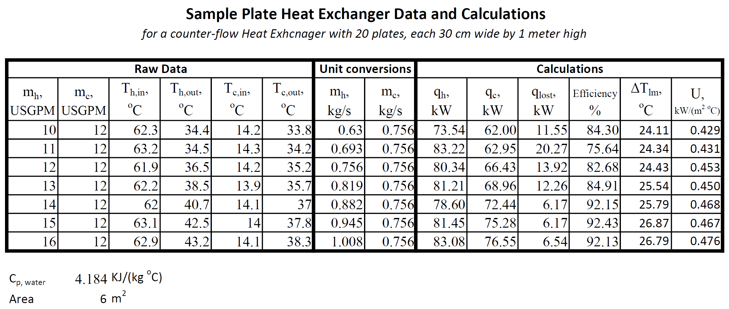
Figure 7: Sample spreadsheet for plate heat exchanger calculations.