Vol. 2, No. 1 (June 2024)
Sienci Labs: Managing Production (Push or Pull?)
Fatih Yegul; Stephen Thomson; and Joshua Hunchak
All figures in Canadian dollars unless otherwise noted.
It was a lovely day in late May 2022, and operations were running smoothly for Kye Allen, Inventory and Logistics Manager, Sienci Labs (SL), Waterloo, Ontario, Canada, when he was first introduced to the idea of switching to a visual pull production system by his former professor, Dr. Fatih Yegul, at Conestoga College, Kitchener, Ontario. The first half of 2022 had been hectic for SL, a privately owned company that produced computer numerical control (CNC) machines for the hobbyist market. SL had been struggling with supply disruptions that caused lengthy delays in product shipments. Allen had been working on preparing the new material requirements planning (MRP) system for implementation during those months and was now ready to go live. At the same time, the company had just launched an applied research project to optimize SL’s production capacity based on lean production principles under the guidance of Yegul and Stephen Thomson, Director of the Centre for Supply Chain Innovation, Conestoga College.
With the new MRP system, Allen aimed to control the assembly operations on the shop floor and have a firm grip on the supply of raw materials and parts. Most MRP systems, by design, assume a make-to-stock environment and tend to push production flow through work orders issued to shop floor employees. However, in the first weekly meeting of the research project, Yegul and Thomson asked Allen to explore the feasibility of moving to a visual make-to-order production management system based on pull principles instead of using work orders. While it would require a radical shift in his plans, a pull system also had several advantages. Allen was in favour of the pull system but wasn’t sure if it was the right time to switch to a make-to-order approach when the company was in the middle of an MRP implementation. Even if his analysis indicated that it was the right time, would he be able to convince Andy Lee, Chief Executive Officer, SL, to move to the pull system? Lee expected Allen to make a recommendation in the next couple of weeks.
Hobbyist CNC Market and Sienci Labs (SL)
Early in the 20th century, CNC[1] technology was primarily used in industrial settings, inaccessible to hobbyists and small businesses. SL emerged from research and testing to create low-cost mechanical systems for rapid prototyping tools like CNC machines, 3D printers, and laser cutters. As a result of such research, the CNC machines, which for decades had only been used in factories due to their high investment costs, became available to hobbyists or small business owners starting in the 2010s, creating a new growing market for such products. SL’s vision was to make automated manufacturing and rapid prototyping technologies accessible for both technical and non-technical producers alike. With SL’s CNC machines, users could cut and engrave into almost any of the most readily available materials with an impressive level of detail.
SL was a small business in Waterloo, Ontario, Canada, founded in 2016, assembling its first products in a garage. SL was then featured on Kickstarter,[2] which brought a boost of capital, allowing the company to move to a larger facility and expand production to meet the increased demand.
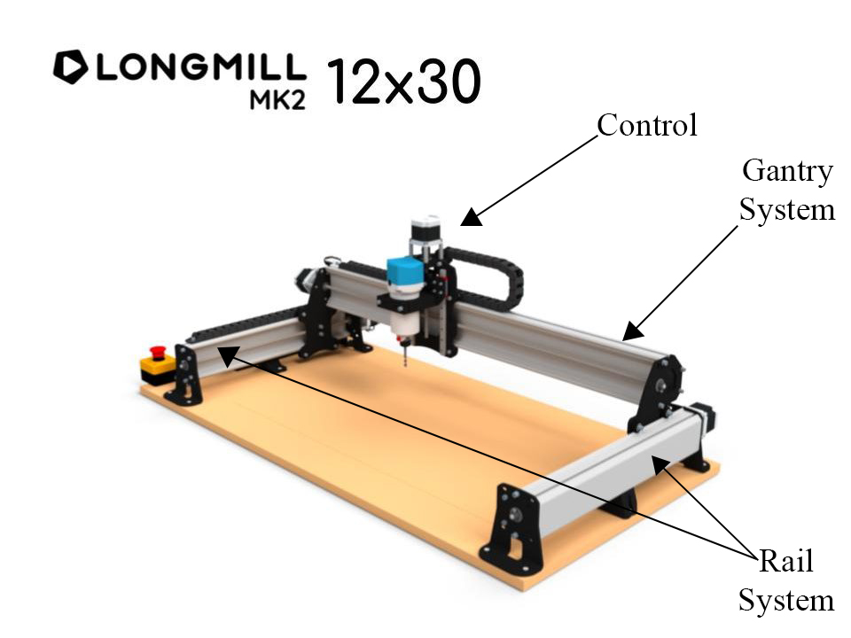
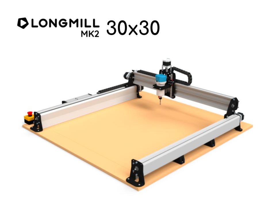
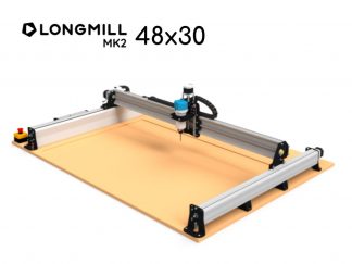
The annual sales growth allowed SL to develop three complete versions of its product called the LongMill Benchtop CNC, Mill One, MK1, and MK2. The latest version of the MK2 featured two different sizes: 12 30 inches and 3030 inches. SL had recently announced the release of a larger third size (4830 inches), which created excitement among the customer base, and the operations were mainly ready to go with the assembly. See Exhibit 1 – Production Photos and Information (LongMill) for photos illustrating the main features of the MK2 LongMill products. Although the rapid expansion came with challenges, SL overcame these challenges thanks to its tight-knit group of employees and family-like atmosphere. The accommodating culture and small size of the company enabled SL to adapt to new situations efficiently.
SL delivered high-quality CNC machines and mainly received positive feedback from its clientele regarding customer service. Transparency was one of SL’s greatest strengths, allowing customers to access nearly all information on the machine and its parts, including valuable training resources for those new to using CNC machines and design software.
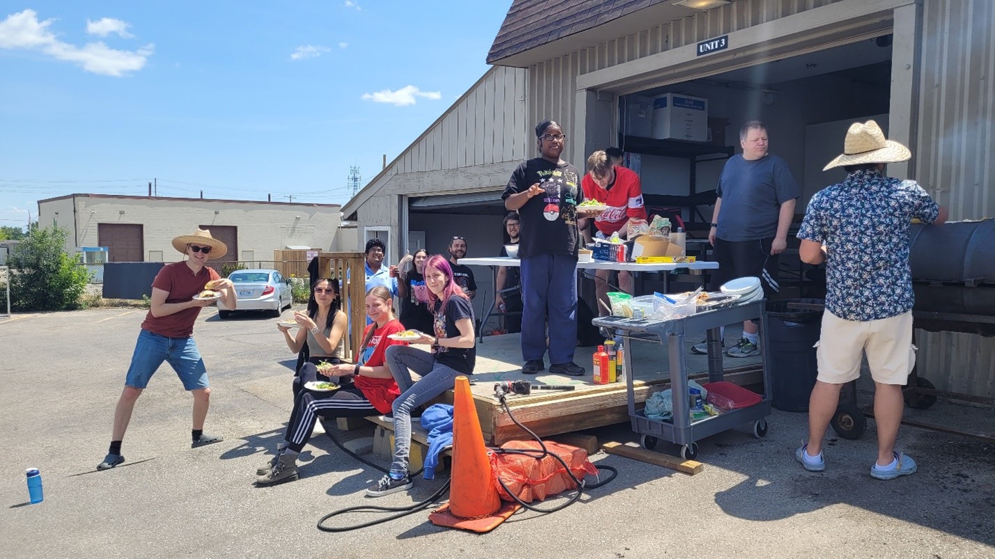
Customers appreciated the family-like working environment of SL, where it was evident that employees enjoyed their jobs and had a passion for the product they offered. For example, several employees owned a CNC and therefore possessed excellent hands-on experience, allowing them to answer customers’ questions confidently and share tips that could only come through the actual use of the machines.
SL sold an average of 6 CNC machines per day to more than 40 countries. The demand pattern showed some seasonality, with more sales during the winter months. During some winter weeks, SL sold an average of approximately 14 machines per day. SL was expecting some increase in demand due to their recent investment in marketing efforts. Accordingly, SL wanted to plan for a throughput of 20 machines per day.
SL’s key suppliers were located in Canada, the United States, China, and Europe. SL employed some 25 people, about one-third of whom worked on the shop floor. SL had two managing partners, an operations manager, an inventory & logistics manager, a dedicated sales & marketing team, an accountant, and a design team.
Kye Allen
Allen was an experienced tennis instructor before studying in the international business management degree program with a supply chain management major at Conestoga College. He worked in the field of logistics during his co-op placement with a beverage production company. He was passionate about building a career in production and inventory management when he applied for his position at SL.
Production and Sales Processes
LongMill was composed of three main components: the rail system, the gantry system, and the control board, each of which included several parts (see Exhibit 1 ). LongMill was a customizable product with fixed as well as variable components that customers chose based on their needs and budgets. See Exhibit 2 – Production Process Flow for a process flow chart that depicts the production and assembly process.
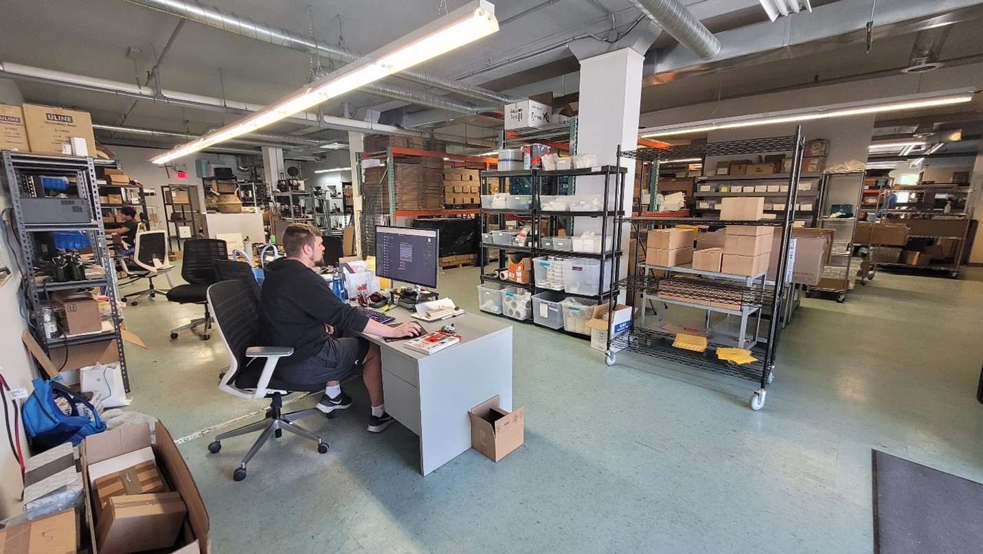
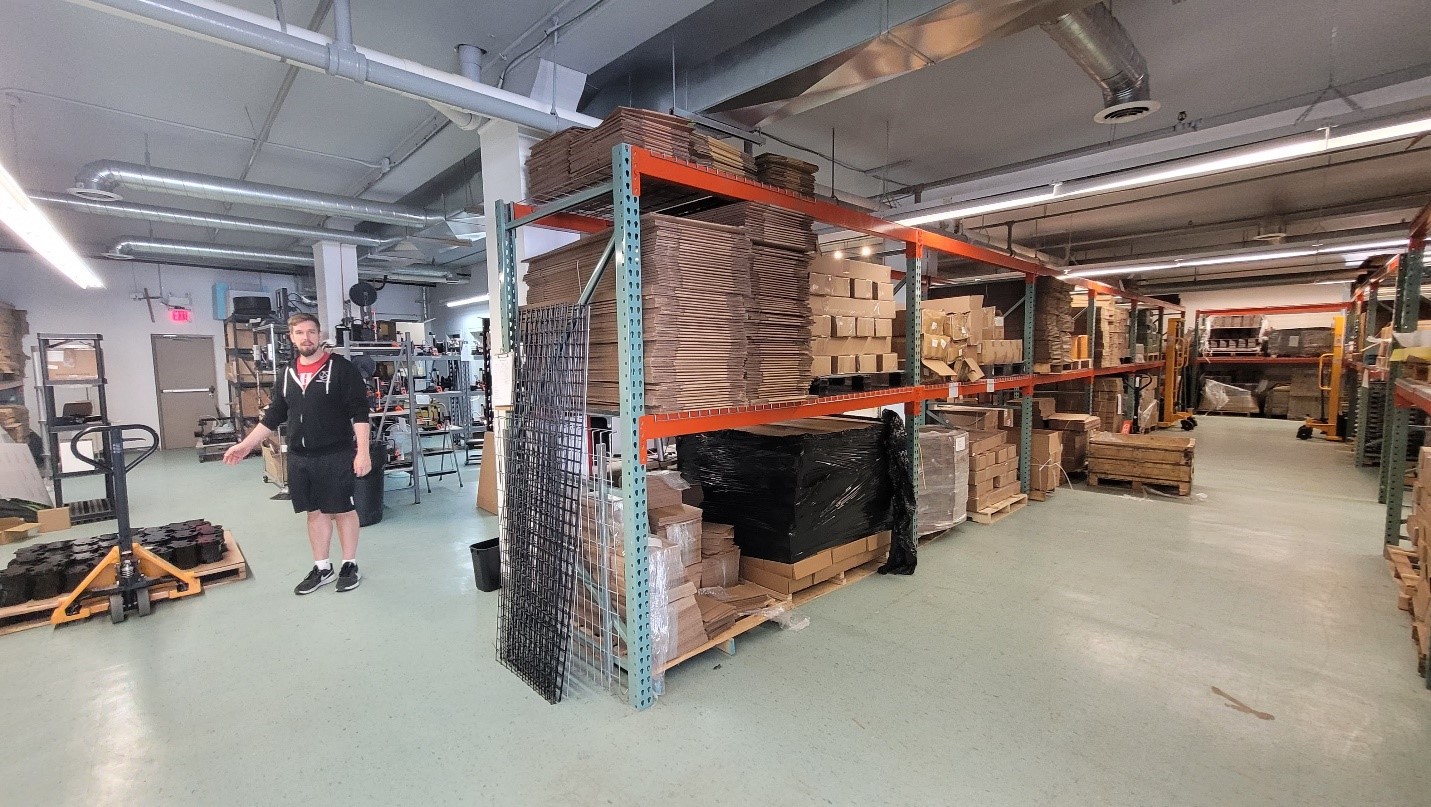
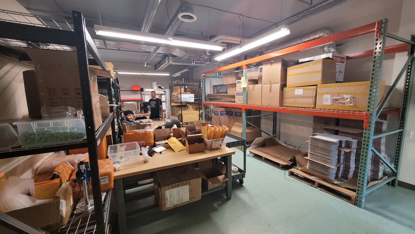
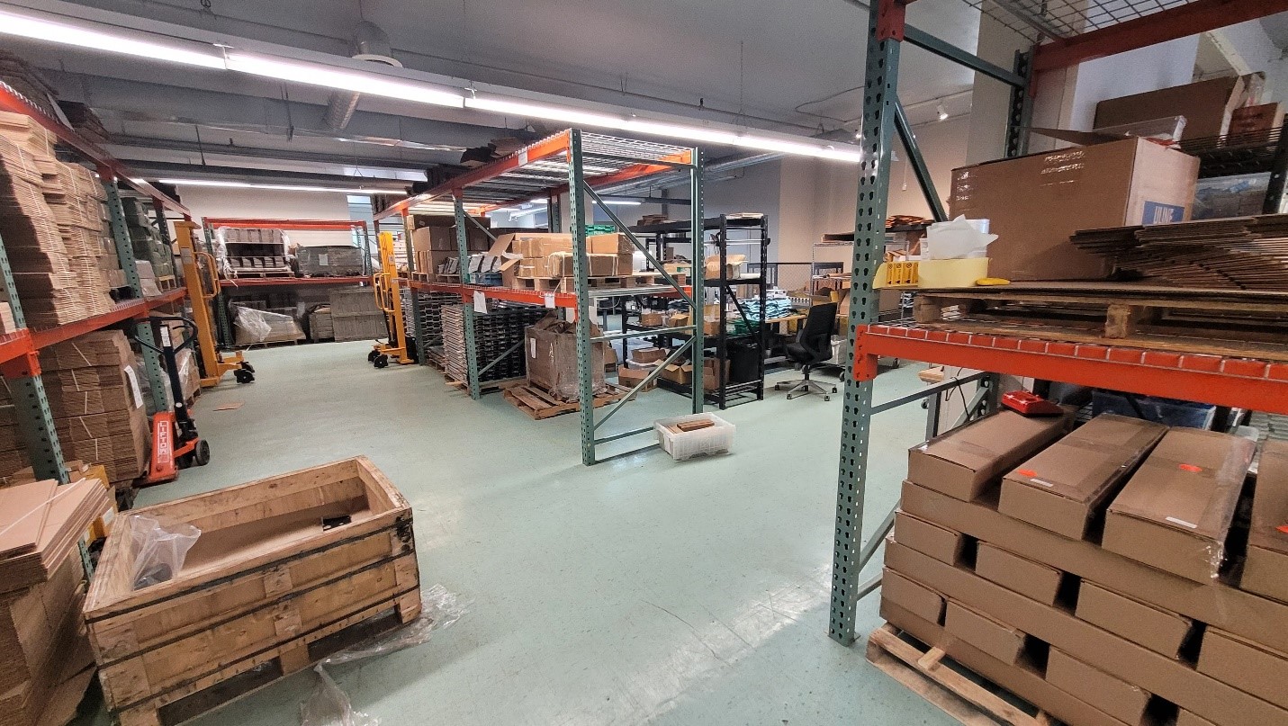
The process contained a slow flow of parts and subassemblies moving toward the packaging & shipping area. However, this reduced flow rate was not apparent to an observer due to the batching system (explained in the next section) that created large amounts of work-in-process (WIP) inventory scattered around the facility. See Exhibit 3 – Facility Layout and Photos and Exhibit 4 – Current State Value Stream Map, which provide a snapshot of WIP inventories at the time.
SL handled its sales through the cloud-based WooCommerce platform and managed the shipments using ShipStation, another cloud-based platform. These two platforms allowed seamless order tracking and easy customization of products by the customers before they placed their orders. SL gave customers three options to ship the products; 1) expedited by UPS for urgent deliveries (2 to 3 business days), 2) standard by UPS (5 to 7 business days), or 3) Canada Post express delivery for customers in Canada (2 business days). The customers picked one option after reviewing the price estimate (based on the weight and size of the order) shown at checkout. SL shipped 70% of the orders via UPS, 25% via Canada Post, while 5% of the products were picked up by the customers from SL’s location.
SL manually tracked and managed its production processes and inventories with the help of spreadsheet software that had no integration with sales and shipment processes. Purchasing transactions were also carried out manually with e-mails and spreadsheets with no integration with manufacturing. A cloud-based accounting software package handled the invoice and payment transactions.
Background of the Challenge
Lee hired Allen in October 2021 to establish an efficient inventory management system and to fix their supply issues. SL’s founders had created a successful business within just a few years. They quickly upgraded from operating in a garage to their current 8,000 sq. ft. location, selling more than two thousand CNC machines annually.
Managing the operations using spreadsheets was not complicated when the sales numbers were small, and the CNC machines were shipped from their garage. As the sales grew fast, SL needed a bigger space for the assembly of the machines. To catch up with the growing demand, SL introduced a batching system, in which it calculated the needs for the forecasted sales every six months and ordered all required parts and materials at once. It assigned numbers to each sales batch. For example, if the company estimated to sell 1,000 units in the first half of 2022, it would designate them “Batch 5” and order enough materials for the batch to assemble 1,000 CNC machines. Each CNC machine consisted of numerous purchased parts with varying lead times, from a few days to a few months. Therefore, to ensure the timely arrival of all required materials, SL had to order materials well in advance.
This batching system required less effort than a conventional supply & inventory management system, but also created some challenges. For example, customers could purchase individual items as add-ons to their existing CNC machines or for repairing them. The batch calculations were made based on the forecast of CNC machine sales, and it was not easy to estimate accurate safety stock numbers to cover the individual part sales. In some cases, the suppliers shipped wrong or defective parts, which caused disruptions in production schedules. Defects were also created during the production and assembly processes, which were set aside for further examination later. Late shipments by suppliers or transportation delays could trigger lengthy production interruptions. Worldwide supply chain disruptions caused by unprecedented global events, such as the COVID-19 pandemic or labour shortages at major international ports, further exacerbated the effects of such issues for SL.[3]
SL also used the same batching system for running its assembly line. For any given batch, at each workstation, employees would produce as many parts or subassemblies as required by that batch unless constrained by space availability. SL did not have enough employees to manage all workstations simultaneously. Most employees had the skills and the training to run more than one workstation. Thus, some workstations would operate at full speed on a given day while the other stations remained idle.
Another consequence of the batching system was the need for space to hold the inventory for extended periods. SL’s current lease was to expire late in 2023, and management was already considering moving to a larger facility.
SL did not digitally track the WIP inventory numbers. The operations manager would visually monitor the accumulation of processed parts and assign workers to other stations when he decided enough parts were produced at a given station. There was no way to determine the exact number of WIP inventories for any part unless they were all manually counted. Furthermore, the system did not offer transactional production data, which made it difficult to measure employee performance or determine standard processing times for tasks. Allen conducted some limited work-study analysis (by observing workers with a stopwatch) to estimate partial baseline figures on the standard times. However, he could not verify the figures against actual work completed daily on the shop floor.
Occasionally, SL was required to stop product shipments due to missing components. At those times, workers continued to generate WIP inventory in other stations while waiting for the parts to arrive. A backlog of product shipments would then pile up. When the missing part was received, the shop floor workers would switch into emergency mode to get caught up: some employees worked on processing the missing piece and all the others worked at packing & shipping stations to deliver as many CNC machines as possible to reduce the backlog quickly.
Lee hired Allen to fix these chronic issues and minimize the supply disruptions by introducing a new production and inventory management system. After analyzing the production flow, inventory management practices, and procurement routines, Allen decided that implementing an MRP system would resolve SL’s challenges. Allen discussed his findings and plan with Lee, who found them agreeable and gave his approval.
MRP Selection
The next job for Allen was to select the most suitable MRP system from a saturated off-the-shelf software market. Thanks to Lee’s assistance, it did not take them long to settle on Katana, a sister product to their e-commerce platform, WooCommerce. Lee had briefly reviewed Katana already because he had noticed the product was listed among the compatible platforms with WooCommerce. Allen explained the selection process:
Katana was [an MRP] software that Andy had played around with and was interested in. I looked at other software systems, and they were either too robust for what we needed, were not robust enough, or the price point was too high. We initially looked into [the MRP module of] Oracle, which is considered the gold standard, but that was both too expensive and too robust for the size of our company. Other options were Fishbowl and Epicor, to name a few.
The MRP implementation plan was seemingly simple. Allen would enter the parts data, BOMs (Bill of Materials), workstation data, assembly routes, and current inventory numbers into the MRP system. The MRP system would then create all the necessary purchase and work orders based on sales transactions, lead times, and reorder points. Employees would operate as instructed by MRP work orders and would enter the number of parts they processed, as well as their start and finish times, into the MRP system before switching to another work order. (See Exhibit 5 – Production/Work Order.)
Early in 2022, SL subscribed to cloud-based Katana with only one “full-access” user license to configure and test the software before going live with two more “full-access” and three “shop floor operator” user licenses. With the less-costly shop floor operator licenses, employees could access the work orders to plan their workdays and enter their production data as they switched between tasks. Thus, Lee and Allen concluded that the monthly subscription fees for Katana (estimated to be around $600/month) were reasonable for their budget.
As Allen made progress with configuring the MRP system, he stumbled upon some small but tricky technical challenges, such as the proper way of entering the product BOMs and routers (order of processes) into the new platform. To get some expert advice, he contacted Yegul, his operations management professor from Conestoga College, who had taught him about MRP systems. Yegul had significant industry experience implementing MRP and enterprise resource planning (ERP) systems. They exchanged ideas via email and online meetings before Yegul paid a visit to SL for first-hand observation of what Allen was aiming to achieve. Yegul was an advocate of lean management methodology, and he believed in the importance of Gemba walks, which were “a lean management practice for grasping the current situation through direct observation and inquiry before taking action.”[4]
Yegul agreed to help his former student resolve the complications of the new system implementation and suggested they apply for a research grant, which could offer them more resources to understand the challenges and tackle them using lean production methodology. Once Allen received approval from Lee, they submitted a grant proposal,[5] which was accepted and allowed them to hire an international business management degree program co-op student from Conestoga College, majoring in supply chain management. Thomson agreed to act as the project manager, while Yegul served as the principal investigator. Yegul visited SL a second time, accompanied by Thomson, to better understand the production system before the project kick-off meeting. During that visit, Allen met with Yegul and Thomson to discuss his goal of having stabilized production, visibility of inventory across the different stages, and a system that was simple and easy to execute.
Late in May 2022, during the project kick-off meeting, Yegul and Thomson recommended Allen consider switching to a pull-based visual production management system instead of the push-based MRP system, to which Allen had devoted considerable effort for the past few months. The recommendation did not necessarily involve scrapping the Katana MRP software, but customizing its work order structure to comply with the pull system. Although it would require Allen to redesign the production and inventory management system, he agreed to set up a call with Katana support staff to explore the possibility of customizing Katana to fit the pull approach.
Allen wanted to implement the MRP work order system to monitor the changes in inventory quantities in real time and analyze employee performances. The same objectives also applied to the proposed pull system. In a typical MRP system, sales forecasts, lead times, and reorder points are entered as main inputs to calculate the required quantities and timings for purchase orders, as well as shop floor work orders based on BOMs. SL would use production numbers from its batching system as the sales forecast and issue the purchase and work orders accordingly.
Instead of using forecasts, the proposed pull system would require SL to produce only as many as was needed to replenish the inventory safety stock levels based on the actual customer demand. Yegul and Thomson understood the challenges in supplying the necessary parts with longer lead times and shortages. Therefore, they advised Allen to implement the pull system initially for the production processes before using it for purchasing operations. At the time of discussion, supply lead times, quantities, and quality were experiencing variations and instability, which did not provide useful data upon which to base a pull-based purchasing strategy. Therefore, SL would continue to use the batching system for procuring parts until the team acquired enough tacit knowledge and experience in the pull production system. They hoped the global supply chain challenges would stabilize during that period.[6]
The pull system would utilize a simple Kanban system with a cautious amount of buffer between workstations that would drastically reduce the WIP inventory quantities. According to their estimates, some 25 bins in different sizes acting as Kanbans would be needed between stations (costing about $20 per bin). They proposed investigating the feasibility of combining some adjacent workstations to eliminate further WIP inventory. In lean management philosophy, inventory was one of the primary waste categories that should be minimized because it did not add any value to the products and concealed production problems. Kanban containers would serve as work orders, such that parts would only be produced when a bin was empty, which became the signal to the workstation to produce a pre-determined batch size to go into the empty container. Based on customer orders, packing & shipping employees would pull parts from the preceding stations’ Kanban containers. Each process would repeat this pulling mechanism from the prior processes. There would be at least two Kanban containers between all workstations for all parts. Employees would regularly check the workstations for empty containers and would run those workstations to fill them. If there were no empty containers in a workstation, that workstation would remain idle. In the meantime, the employees could run the other workstations with empty containers. To make things smoother, Yegul and Thomson suggested SL pick a couple of stations to pilot the Kanban system before restructuring the entire production system.
Allen, Yegul, and Thomson met with a Katana representative to discuss whether the MRP platform’s work orders could still be used with the pull system, allowing Allen to collect data on employee performance. Katana’s representative reminded them that the platform typically issued work orders as part of the MRP process. Nevertheless, he added that with some tweaks Allen could also create work orders to monitor production within a Kanban-based pull system.
See the Exhibit 6 – Case Study Video Clips in which project stakeholders share their takes on the dilemma Allen experienced.
Going Forward
Allen was at a crossroads. He could either ignore his professor’s recommendation to switch to a Kanban-based pull system and insist on his original plan to go live with the MRP system, or he could adopt the recommendation and restructure the production system based on a pull model. If he opted for the pull system, he wondered if it was still a good idea to implement the MRP system and the work orders? It had already been several months since Allen started working on the new system, and Lee was expecting to see some results. Allen needed to decide sooner rather than later.
Exhibits
Exhibit 1 – Product Photos & Information (LongMill)
The LongMill MK2 is a powerful and affordable hobby CNC router perfect for any workshop. Based on your needs, you can choose from one of its three sizes: 1230, 3030, and 4830. The machine size roughly corresponds to its cutting area in inches and each machine has 125mm of Z-axis travel.
[back]
Exhibit 2 – Production Process Flow
Explanation of Production Process Flow
- 1.1: Raw aluminium extrusion is cut into three pieces per machine for each side. (2 for Y axis – 1 for X axis). These pieces are now called rails.
- 1.2: Rails are tapped on all corners on both sides creating rail threads.
- 1.3: Rails are inspected against any scrapes/chips and tested for performance. Drag chain attached to the rails.
- 1.4: Rails are packaged together and colour coded based on what size of machine they belong to.
- 1.5: Packing and shipping all of the subassemblies and parts from all of the other processes to fulfil customer orders. Customers assemble the CNC on a board they acquired themselves. Smaller size CNCs ship in one box, while the biggest size (48×30) requires two boxes.
- 1.6: Getting the drag chain ready for assembly in process 1.3. Lead screws are added that are needed for final assembly of the CNC machine.
- 1.7: Machine feet are needed to assemble rails to the final CNC machine. They are manufactured by a local subcontractor.
- 1.8: Hardware bags are packed with all of the small parts necessary to assemble the machine (screws, bolts, nuts, washers, plastic pieces, etc.).
- 1.9: Hardware bag parts are brought together in one station for packing.
- 1.10: The variable box is packaged with four core items. A control board, a motor mount, a router mount, and an e-stop. As the name implies, the variable box will also include any optional accessories customers order, such as bits, touch plates, and replacement hardware.
- 1.11: Control board assembly takes three steel pieces (each cut for different sides), a control board, and an acrylic top as its core items.
- 1.12: Control board is tested to ensure proper movement and function on all hypothetical axis motors.
- 1.13: Router mounts are two steel pieces that attach together to house the router for any projects.
- 1.14: The welcome pouch contains the necessary instructions and tools to build the machine.
- 1.15: Gantry assembly involves screwing together an X-gantry, a Z-gantry, and two linear guides.
- 1.16: Gantry packing places the gantry assembly with two Y-gantries into a box.
- 0.1: The 3D printing station allows for many parts to be produced in house cost-efficiently.
- 2.1: The dust shoe is a product that is designed to keep the workspace as clean as possible while the CNC is processing a piece. It consists of a 3D printed base, an acrylic piece, magnets, and bristles. Each part is attached to the base with screws.
- 2.2: The inductive sensor kit is an accessory that allows the machine to detect when the machine reaches certain areas of the workspace. It contains three sensors packed alongside the mounting accessories.
- 2.3: The touchplate is an accessory enabling the CNC to determine where it is within the workspace (x,y). In this process the touchplate is placed alongside its wires in packaging.
- 2.4: The AutoZero touchplate acts as a device that allows for 3D control for determining which point of the machine the router is at (x,y, and z). The process is nearly identical to the original touchplate.
- 2.5: T-tracks are optional components that enable securing parts on the CNC platform while they are being processed. Some of its components are produced by the 3D printer. Other parts are purchased from suppliers.
- 2.6: Bits are different kinds of tips that do the actual cutting. Bits are sourced from suppliers and already come in the standard packaging that they will be sent to a customer in.
- 3.1: The LaserBeam system is a new optional attachment to the CNC that allows for laser engraving rather than traditional carving. There are many subprocesses and parts that go into this product, but it is a separate entity from the LongMill CNC product itself. Details of this process were out of scope for the purposes of this case.
- For further clarification, visit SL’s online product catalogue, which includes the photos of the parts mentioned in the process flow chart explanations.
[back]
Exhibit 3 – Facility Layout & Photos

[back]
Exhibit 4 – Current State Value Stream Map
[back]
Exhibit 5 – Production/Work Order
A production work order is a document used in manufacturing to communicate the details of a product that needs to be produced, including the specific requirements, materials, and production processes. It is essentially a set of instructions that serves as a roadmap for the production process, ensuring that the finished product meets the required specifications and standards.
Here’s a basic outline of how a production work order typically works:
- Initiation: A production work order is initiated by a customer’s purchase order, a sales order, or a company’s internal demand for a specific product.
- Planning: The production team then reviews the production work order and plans the production process, including determining the materials, tools, and manpower required.
- Scheduling: The production team schedules the production run, taking into account the availability of resources and ensuring that the production meets the required delivery date.
- Execution: The production team executes the production process, following the instructions outlined in the work order. They also record the progress and any deviations from the planned process.
- Completion: Upon completion of the production process, the production team updates the work order to reflect the actual materials used, labor costs, and other relevant information. The finished product is then shipped to the customer or stored in inventory.
A production work order is an important tool that helps to ensure that the production process runs smoothly and that the finished product meets the required standards. It helps to coordinate the activities of different departments within a manufacturing organization and provides a clear record of the production process for future reference.
[back]
Exhibit 6 – Case Study Video Clips
Clip 1
Kye Allen, Inventory & Logistics Manager, describes their journey with the MRP system. (57 secs)
Source: Open Access Teaching Case Journal. (2024, April 30). Clip 1. [Video]. YouTube.
Clip 2
Kye Allen, Inventory & Logistics Manager, describes why SL considered using work orders to manage production. (27 secs)
Source: Open Access Teaching Case Journal. (2024, April 30). Clip 2. [Video]. YouTube.
Clip 4
Kye Allen, Inventory & Logistics Manager, talks about the time when he was recommended to use Kanban instead of work orders. (36 secs)
Source: Open Access Teaching Case Journal. (2024, April 30). Clip 4. [Video]. YouTube.
Clip 9
Josh Hunchak, co-op student/researcher, explains Kye’s dilemma in deciding which system to use (MRP or Kanban). (53 secs)
Source: Open Access Teaching Case Journal. (2024, April 30). Clip 9. [Video]. YouTube.
Clip 12
Andy Lee, CEO & Co-founder, explains their motivation to engage in this research project. (42 secs)
Source: Open Access Teaching Case Journal. (2024, April 30). Clip 12. [Video]. YouTube.
Clip 19
Patrick, Operations Manager, talks about the problems they had before the project started. (53 secs)
Source: Open Access Teaching Case Journal. (2024, April 30). Clip 19. [Video]. YouTube.
[back]
Image Descriptions
Exhibit 1 – Product Photos & Information (LongMill) Image 1
An image of LongMill MK2 on white background. Device consists of a rectangular platform 12 inches by 30 inches with a rail (or long bar the length of the platform) on the right and left short sides. At the far long side of platform, the gantry (a long bar the length of the platform) is perpendicular to and attached to the top of the rails, connecting them. The control board and router are mounted on the middle of the gantry, with the router tool pointing down toward the platform. A red button is on the far left corner of the platform. The control board, gantry system, and rail system are labelled.
[back]
Exhibit 1 – Product Photos & Information (LongMill) Image 2
An image of LongMill MK2 on white background. Device consists of a square platform 30 inches by 30 inches with a rail (long bar the length of the platform side) on the right and left sides. At the far side of the platform, the gantry (a long bar the length of the platform) is perpendicular to and attached to the top of the rails, connecting them. The control board and router are mounted on the middle of the gantry, with the router tool pointing down toward the platform. A red button is on the far left corner of the platform.
[back]
Exhibit 1 – Product Photos & Information (LongMill) Image 3
An image of LongMill MK2 on white background. Device consists of a rectangular platform 48 inches by 30 inches with a rail (long bar the length of the platform short side) on the right and left sides. At the far long side of platform, the gantry (a long bar the length of the platform long side) is perpendicular to and attached to the top of the rails, connecting them. The control board and router are mounted on the middle of the gantry, with the router tool pointing down toward the platform. A red button is on the far left corner of the platform.
[back]
Exhibit 1 – Product Photos & Information (LongMill) Image 4
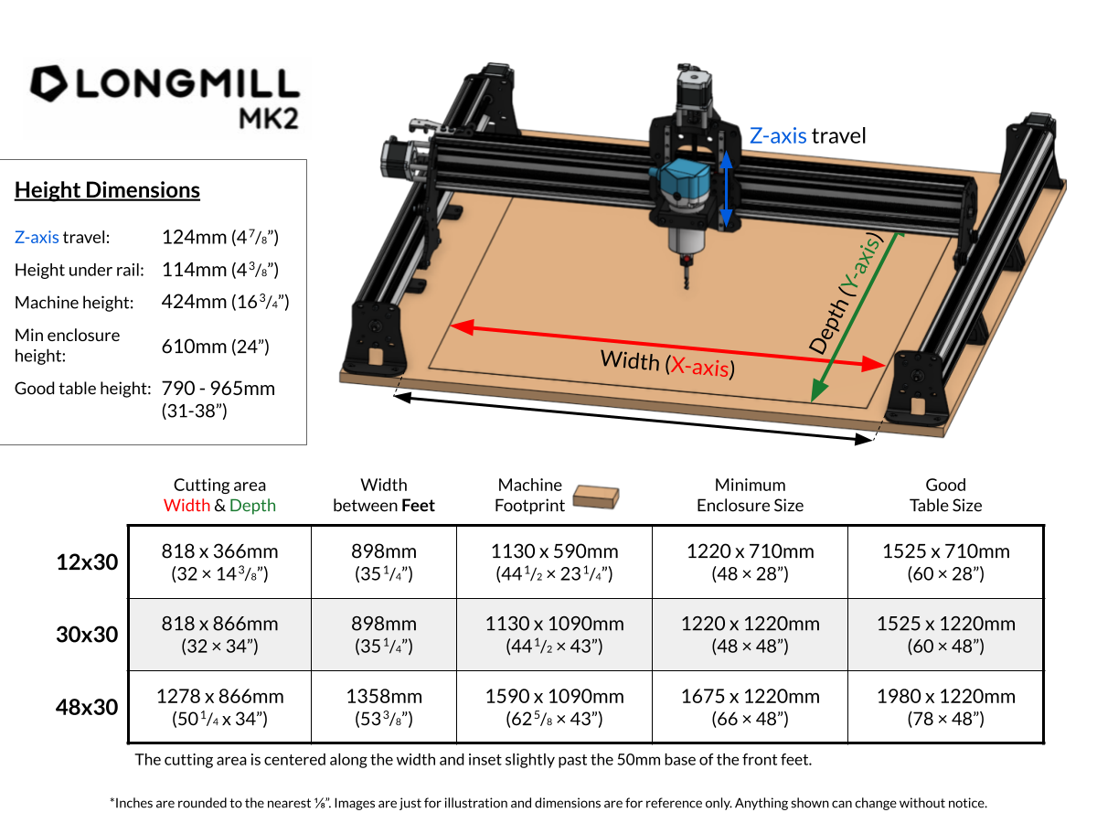
An illustration of the LongMill MK2 consisting of a rectangular platform with a rail (long bar the length of the platform short side) on the right and left sides. The gantry (a long bar the length of the platform long side) is perpendicular to and attached to the top of the rails, connecting them. The gantry is labelled “Z-axis travel.” The control board and router are mounted on the middle of the gantry, with the router tool pointing down toward the platform. A lined box on the platform shows the cutting area: A two-sided arrow indicating the long side of the box (from rail to rail) is labelled “Width (X-axis)” and a two-sided arrow parallel to the rails indicates the short side of box and is labelled “Depth (Y-axis).” And additional unlabelled two-sided arrow runs the length of the platform beyond the box lines, indicating the distance between the rails.
A legend box on the right side of the illustration includes the following under the heading Height Dimensions
- Z-axis travel: 124mm (4 7/8″)
- Height under rail: 114mm (4 3/8″)
- Machine height: 424mm (16 3/4″)
- Min enclosure height: 610mm (24″)
- Good table height: 790–965mm (31–38″)
A table below the illustration includes the specific dimensions of each size CNC router.
| Size | Cutting area Width & Depth | Width between Feet | Machine Footprint | Minimum Enclosure Size | Good Table Size |
|---|---|---|---|---|---|
| 12×30 | 818 × 366mm (32 × 14 3/8″) | 898mm (35 1/4″) | 1130 × 590mm (44 1/2 × 23 1/4″) | 1220 × 710mm (48 × 28″) | 1525 × 710mm (60 × 28″) |
| 30×30 | 818 × 866mm (32 × 34″) | 898 mm (35 1/4″) | 1130 x 1090 mm (44½ × 43″) | 1220 × 1220mm (48 × 48″) | 1525 × 1220mm (60 × 48″) |
| 48×30 | 1278 x 866mm (50 1/4 × 34″) | 1358mm (53 3/8″) | 1590 x 1090 mm (62 5/8 × 43″) | 1675 × 1220 mm (66 × 48″) | 1980 × 1220 mm (78 × 48″) |
Notes below the table are as follows:
The cutting area is centered along the width and inset slightly past the 50mm base of the front feet.
*Inches are rounded to the nearest 1/8 inch. Images are just for illustration and dimensions are for reference only. Anything shown can change without notice.
[back]
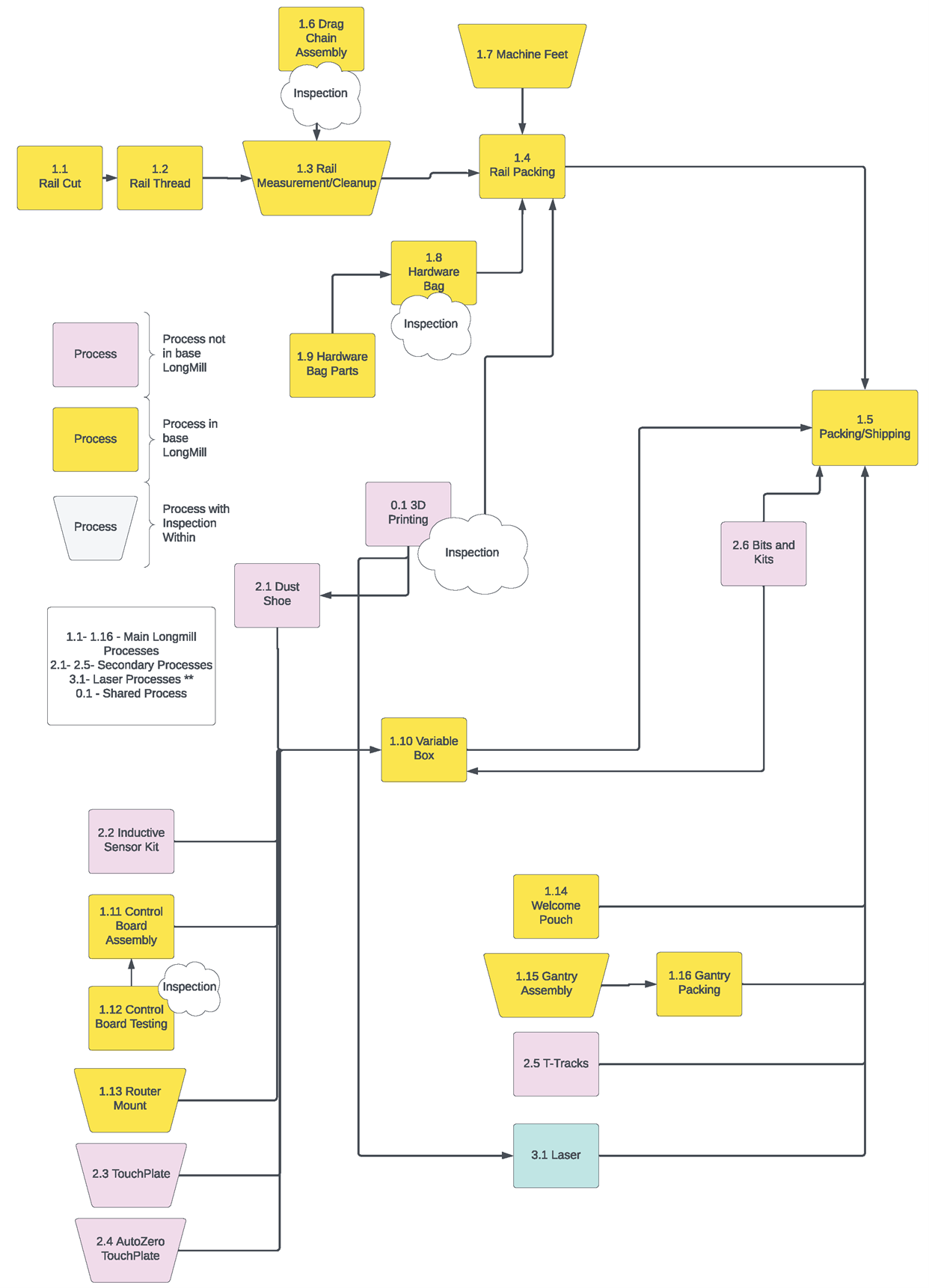
Exhibit 2 – Production Process Flow
The complex flow chart consists of purple boxes representing a process not in base LongMill and yellow boxes representing process in base LongMill; trapezoid boxes in both colours represent processes with an inspection within it. Additional inspections are represented in cloud shapes.
1.1 to 1.16 are main LongMill processes, 2.1 to 2.5 are secondary processes, 3.1 is a laser process and 0.1 is a shared process.
- The flow chart begins at the top with yellow square 1.6 Drag Chain Assembly with Inspection cloud flows down to yellow trapezoid 1.3 Rail Measurement/Cleanup.
- Below and at left, yellow square 1.1 Rail Cut flows right to yellow square 1.2 Rail Thread, which flows right to yellow trapezoid 1.3 Rail Measurement/Cleanup.
- 1.3 Rail Measurement/Cleanup flows right with a small s-turn to yellow square 1.4 Rail Packing.
- To the right of 1.6 Drag Chain Assembly, yellow trapezoid 1.7 Machine Feet flows down to 1.4 Rail Packing.
- 1.4 Rail Packing flows to the right side of chart and then down to 1.5 Packing/Shipping.
- From the middle of the chart, another line flows to 1.4 Rail Packing, beginning with yellow square 1.9 Hardware Bag Parts flowing up and to the right to yellow square 1.8 Hardware Bag, with an Inspection cloud. 1.8 Hardware Bag then flows right and up to 1.4 Rail Packing.
- Further down in the chart, an additional line flowing up into 1.4 Rail Packing flows from purple box 0.1 3D Printing with Inspection cloud.
- 3D Printing also flows down and left to purple square 2.1 Dust Shoe, which flows down and to the right into yellow square 1.10 Variable Box in the centre of the chart.
- 3D Printing also flows down to the bottom of the chart and right to teal square 3.1 Laser, which then flows right and up to 1.5 Packing/Shipping.
- 1.10 Variable Box also flows right and up to 1.5 Packing/Shipping.
- On the right side of chart, purple square 2.6 Bits and Kits flows to both 1.10 Variable Box below it and 1.5 Packing/Shipping above it.
- On the lower left side of chart, a stack of boxes each flow right and then up through a shared line into 1.10 Variable Box:
- Purple box 2.2 Inductive Sensor Kit
- Yellow box 1.11 Control Board Assembly
- Yellow trapezoid 1.13 Router Mount
- Purple trapezoid 2.3 TouchPlate
- Purple trapezoid 2.4 AutoZero TouchPlate
- Within this horizontal stack of boxes, Yellow square 1.12 Control Board Testing with Inspection cloud flows up to 1.11 Control Board Assembly
- On the lower right side, a stack of boxes flows as follows up to 1.5 Packing/Shipping:
- Yellow square 1.14 Welcome Pouch flows right to the up line
- Yellow trapezoid 1.15 Gantry Assembly flows to yellow square 1.16 Gantry Packing, which flows right to the up line
- Purple square 2.5 T-Tracks flows right to the up line
- 3.1 Laser flows right to the up line
[back]
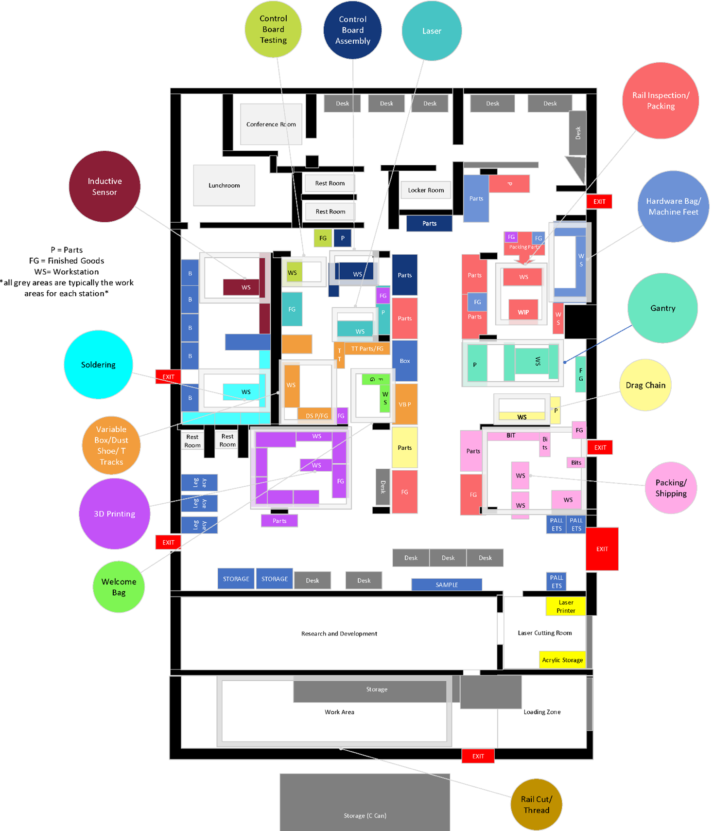
Exhibit 3 – Facility Layout & Photos
A floor plan map of the Sienci facility consisting of several coloured boxes highlighting different functional areas and stations. Around the outside of the map, key functions are identified with arrows and coloured labels. At the top of the map is a conference room, lunchroom, several desks, restrooms, and a locker room. In the middle are areas for parts storage, workstations, finished goods, and work-in-progress. The lower portion of the map includes large open areas labelled research and development, storage, general workspaces, and a loading zone. Building exit doors marked in red appear on the left side, three exits on the right, and one exit at the bottom.
Different areas throughout the map are colour-coded to the labels around the outside of the map. The labels clockwise from the top include
- control board testing
- control board assembly
- laser
- rail inspection/packing
- hardware bag/machine feet
- gantry
- drag chain
- packing/shipping
- rail cut/thread
- welcome bag
- 3D printing
- variable box/dust shoe/T tracks
- soldering
- inductive sensor
[back]
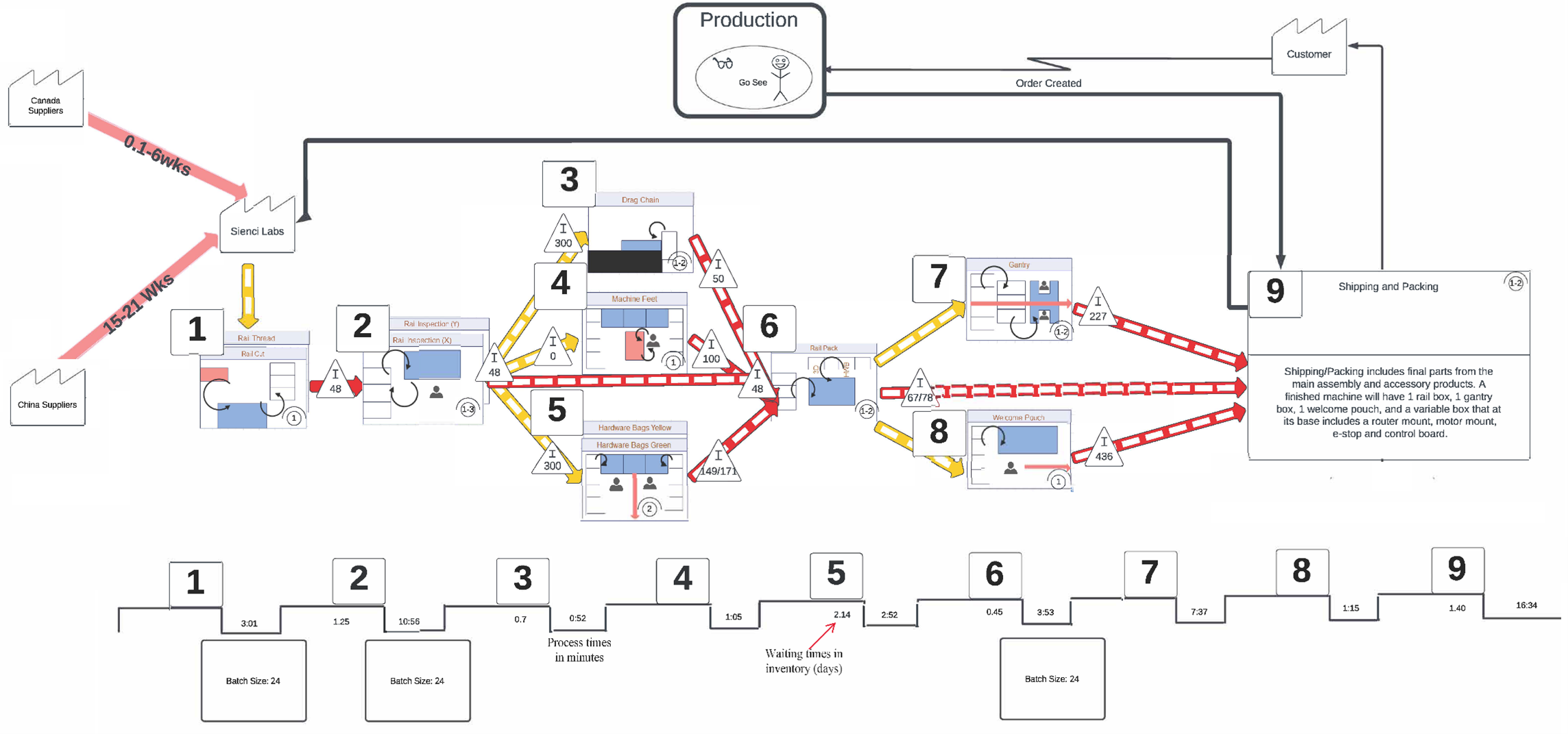
Exhibit 4 – Current State Value Stream Map
At centre of the image is a schematic of the current processes in Sienci Labs, from left to right. Each process is represented with a mini diagram of the workstation illustrating the cycle and flow of the product. Below the schematic is a timeline that indicates the lead times between each processes, marking process time in minutes and waiting times in inventory. At the right of the schematic, a box labelled Canada Suppliers flows to Sienci Labs in 0.1 to 6 weeks and a box labelled China Suppliers flows to Sienci Labs in 15 to 21 weeks.
From the Sienci Labs box, the schematic begins with process 1 Rail Thread, Rail Cut, and moves through a triangle labelled I 48 to 2 Rail Inspection (Y), Rail Inspection (X). The schematic continues as follows:
- 2 Rail Inspection (Y), Rail Inspection (X) moves through a triangle labelled I 48 into three branches
- 3 Drag Chain through a triangle labelled I 300
- 4 Machine Feet through a triangle labelled I 0
- 5 Hardware Bags Yellow, Hardware Bags Green through a triangle labelled I 300
- A fourth branch travels from 2 past 3, 4, and 5 to 6 Rail Pack through a triangle labelled I 48
- 3 also moves to 6 through a triangle labelled I 50
- 4 also moves to 6 through a triangle labelled I 100
- 5 also moves to 6 through a triangle labelled I 149/171
- 6 Rail Pack moves through two branches to 7 Gantry and 8 Welcome Pouch
- A third branch through the middle moves from 6 to 9 Shipping and Packing through a triangle labelled I 67/78
- 7 moves to 9 Shipping and Packing through a triangle labelled I 227
- 8 also moves to 9 Shipping and Packing through a triangle labelled I 436
At the far-left end of the schematic, 9 Shipping and Packing is a large box with the following text:
Shipping/Packing includes final parts from the main assembly and accessory products. A finished machine will have 1 rail box, 1 gantry box, 1 welcome pouch, and a variable box that at its base includes a router mount, motor mount, e-stop, and control board.
Above the schematic, a long, straight line loops back from 9 to the Sienci Labs box. At the top of the image a large box labelled Production includes a stick figure person and a pair of glass with the text Go See; this box flows to the right and down to Process 9. Process 9 also flows up to a box labelled Customer, which flows left through a zig zap labelled Order Created to the large Production box.
The timeline at the bottom of the image includes the numbers 1 to 9 in boxes. A horizontal line travels below these boxes in a checkboard pattern with the process times in minutes above the line and the waiting time in inventory days below the line. Batch sizes appear in large boxes below this line.
Timeline data is as follows:
- Process 1
- Process time (in minutes): 3:01
- Batch size: 24
- Process 2
- Waiting time in inventory (days): 1.25
- Process time (in minutes): 10:56
- Batch size: 24
- Process 3
- Waiting time in inventory (days): 0.7
- Process time (in minutes): 0:52
- Process 4
- Process time (in minutes): 1.05
- Process 5
- Waiting time in inventory (days): 2.14
- Process time (in minutes): 2:52
- Process 6
- Waiting time in inventory (days): 0.45
- Process time (in minutes): 3:53
- Batch size: 24
- Process 7
- Process time (in minutes): 7:37
- Process 8
- Process time (in minutes): 1.15
- Process 9
- Waiting time in inventory (days): 1.40
- Process time (in minutes): 16:34
[back]
References
Lean Enterprise Institute. (2020, July 2). Gemba walk.
Numerical control. (2023, August 13). In Wikipedia.
Ricaurte, F.S. (2022, February 22). Understanding supply chain disruptions during the COVID-19 pandemic. McGill Business Law Platform.
Download a PDF copy of this case [PDF].
Read the Instructor’s Manual Abstract for this case.
How to cite this case: Yegul, F., Thomson, S. & Hunchak, J. (2024). Sienci Labs: Managing production (push or pull?). Open Access Teaching Case Journal, 2(1). https://doi.org10.58067/4bmm-c104
The Open Access Teaching Case Journal is a peer-reviewed, free to use, free to publish, open educational resource (OER) published with the support of the Conestoga College School of Business and the Case Research Development Program and is aligned with the school’s UN PRME objectives. Visit the OATCJ website [new tab] to learn more about how to submit a case or become a reviewer.
ISSN 2818-2030

- CNC (Computer Numerical Control) machines processed a piece of material (metal, plastic, wood, ceramic, stone, or composite) to meet specifications by following coded programmed instructions and without a manual operator directly controlling the machining operation (Numerical control, 2023). ↵
- Kickstarter was an online platform with the mission of helping bring creative projects to life. ↵
- Ricaurte, 2022. ↵
- Lean Enterprise Institute, 2020. ↵
- ARTP grant by NSERC, which was assessed and granted by Conestoga College Office of Research Services. ↵
- Ricaurte, 2022. ↵
