Voltage Tests
You can troubleshoot a problem using either a volt or ohms test. It is most practical to choose voltage testing. With a resistance test, you have to first disconnect the component being tested from the circuit, and while you are removing the wiring you could jostle things and possibly change the circuit, which may temporarily remedy the problem. In other words, you may not really find the problem.
When you use your voltmeter to troubleshoot, you will find either a switch that is open or a load that has failed. You can do this without moving any wires and without changing the circuit in any way. You may then remove the device and double check it with your ohmmeter.
Voltage Drops in Series Circuits
In series circuits, the total voltage is the sum of the individual voltage drops in the circuit, and the equation E = IR is used to calculate the voltage drop across each resistor. Since the current is the same through each resistor, the voltage drop across each resistor is directly proportional to the value of resistance. In other words, the greater the value of a resistor in a series circuit, the higher the voltage drop. Consider the simple series circuit in Figure 1.
Figure 1 – Series Circuit
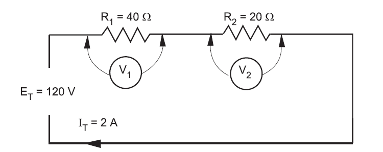
From the values given above, you can easily calculate the voltage drop across each resistor by:
E1 = I1 × R1 = 2 A × 40 Ω = 80 V
E2 = I2 × R2 = 2 A × 20 Ω = 40 V
The voltage drop of 80 V across the 40 Ω resistor is twice the voltage drop across the 20 Ω resistor.
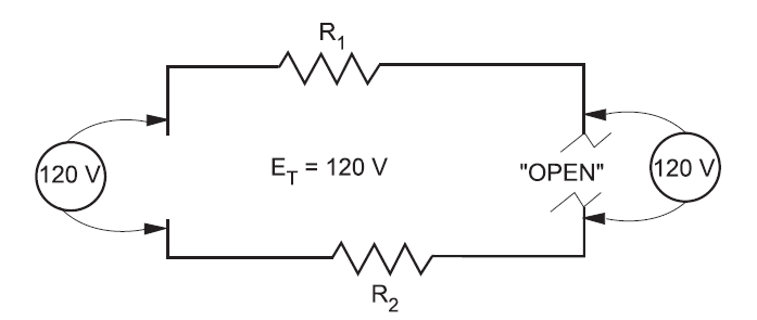
Refer to Figure 2. If an open is introduced between resistors R1 and R2 (for example, by disconnecting a lead), current flow through the circuit is, of course, interrupted. If there is no current flow, the voltage drop across each of the resistive elements is zero (since E = I × R).
However, the potential difference of the source still exists across the open. If a voltmeter is connected across the open, the reading is the same as if it were connected directly across the terminals of the supply source.
Figure 2 – Voltage Across and Open Circuit
In a series lighting circuit, you could easily determine which lamp was burnt open simply by measuring the voltage across the lamp-holder terminals, in succession, until you have measured the total source voltage.
