Troubleshooting Series Components
Sometimes you will be required to troubleshoot a piece of equipment that has stopped working. The first thing you would check for is power. Is the breaker off? Is the switch off? Is there a general power outage?
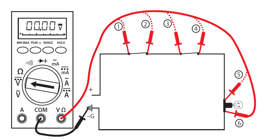
Once you have determined that power is still available you can begin using the multimeter to locate the problem. Starting with the first component or the one easiest to check, work your way through the circuit until you reach the component that shows no voltage reading. This is known as hopscotch voltage readings. Figure 3 illustrates this process. The dashed line indicates where the probe has already been placed and removed.
Figure 3: Hopscotch Troubleshooting
Follow these steps to complete the voltage test procedures with an autorange meter:
- Set the selector dial to the type of current to be tested: AC or DC.
- Once you have determined that the load (shown as a lightbulb) is not working, check for voltage across the light first to verify rule #2 (i.e., if you measure a correct voltage across a load and the load doesn’t work, the load has failed.).
- If you have voltage across the light, then the light has failed. If there are zero volts across the light, then one of the switches or wiring connections in the circuit has failed. If you have a zero reading across the light, continue with the next steps.
- Place the black probe at a grounded component.
- Place the red probe and check for a voltage reading at each test point in order starting at test point 1, verifying power supply.
- Continue working your way through the circuit until you get a zero reading, which would indicate a break in the circuit just before that point.
- Reading at 2 = switch #1 closed, zero at 2 = switch #1 open
- Reading at 3 = wiring to switch #2 good, zero at 3 = wiring to switch #2 open
- Reading at 4 = switch #2 closed, zero at 4 = switch #2 open
- Reading at 5 = wiring to light good, zero at 5 = wiring to light open
- Reading at 6 = load is energized, zero at 6 = the load is open (although you have already checked the load in your first test). If you get to this stage and the load is energized, the only component left that must be faulty is the final wiring from the load to ground.
- Once the open in the circuit has been identified, you can de-energize the circuit, remove the component, and double check the component with your ohmmeter.
- If this is the last test you are doing, turn the meter to “off” and store in a safe place.
Note: There may be other circuits that are energized even though the circuit you are working on is not energized. DO NOT TOUCH THE METER PROBES TO ANY ENERGIZED COMPONENTS WHEN TESTING FOR Ω (RESISTANCE). YOU MAY DAMAGE THE METER.
