Polarity in a Parallel Circuit
Just as in series circuits, electrical current flows “from negative to positive” through each of the load components in a parallel circuit. As illustrated in Figure 6, electrons leave the negative terminal of the source and flow from negative to positive through each of the load resistors. Note that the polarity of each of the resistors is the same as the polarity of the source.
Figure 6 – Polarity in a Parallel Circuit
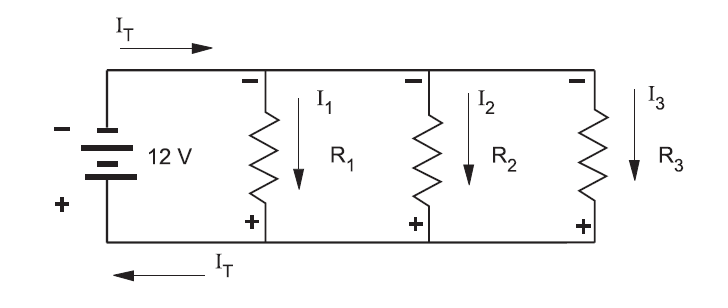
Polarity is always expressed from one point of a circuit relative to another point with a different electrical potential. Note that in Figure 6 the top side of each resistor, which is marked negative, is in effect the same point. No difference in potential exists between any of these like terminals.
Also notice that the individual currents through each resistor (I1, I2, I3) together constitute the total current (IT) drawn from the source. When the total current required to operate each of these parallel loads exceeds the current output rating of the one source, you will need to increase the source output.
Polarity Test for Parallel Voltage Sources
Voltage sources are connected in parallel whenever it is necessary to deliver a current output greater than the current output a single source of supply can provide, without increasing voltage across a load.
- Power sources are connected in series to increase the voltage output.
- Conversely, power sources are connected in parallel to increase the current capacity.
An advantage of parallel-connected power sources is that one source can be removed for maintenance or repairs while reduced power to the load is maintained. If a 6 V battery has a maximum current output of 1 A, and if it is necessary to supply a load requiring 2 A, then you can connect a second 6 V battery in parallel with the first.
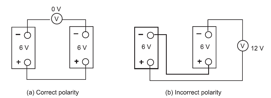
If there is any doubt about the polarity of the two batteries, then you can do a simple voltmeter test for correct polarity.
- Tie one side of the power sources together.
- Before connecting the paralleling jumper between the remaining two terminals, insert a voltmeter between these two points. See Figure 7.
- If the polarity is incorrect (Figure 7b), the voltmeter indicates two times the source voltage, because the equal EMFs aid each other. Do NOT connect across these terminals.
If the polarity is correct (Figure 7a), then the voltmeter indicates 0 V because the EMFs oppose each other. You may connect a paralleling jumper between these two points.
Figure 7: Polarity Test