Introduction to Current Measurements
As you have seen, the procedure for voltage measurements is relatively straightforward. The leads are simply connected across, or are parallel with, the points of voltage to be measured.
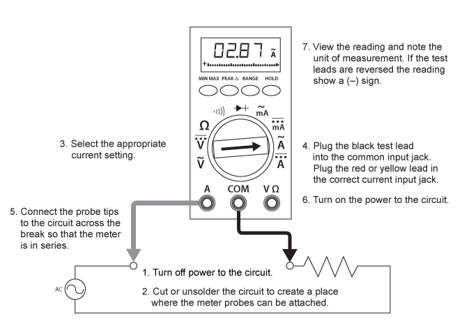
For current measurements, however, the process is slightly more complex. First, the circuit must be opened at the test points and the meter inserted in series at that opening (Figure 5). The total current must flow through the meter. To allow the measurement to be made without disturbing the circuit itself, the current meter has very little internal resistance.
This is where an inexperienced technician must be particularly alert. If the meter is inadvertently connected across a point of P.D. (potential difference) or in parallel with a component instead of in series, the small internal resistance will permit a very large current to flow through the meter resulting in a short circuit. This will most certainly damage the meter severely and perhaps the circuit as well. More alarming is the possibility of causing a dangerous arc flash. The severity of an arc flash depends on a number of factors including but not limited to the distance from the arc flash, the safety equipment worn or more specifically the lack of, the duration of the arc flash as well as the length of the arc flash. For more information on arc flash safety visit www.esasafe.com.
With current measurements, shutting off the power before connecting the meter is essential. You will be disconnecting one end of a wire or component to connect the meter in series. If you leave the power on, you could easily receive a dangerous shock or damage the circuit.
On meters with manual range selection, start with the highest current setting and work your way down.
Figure 5 – Using a Digital Multimeter to Measure Current
Current Measurement Procedures
Follow the steps below to measure current in circuits of 0-30V:
- Before testing begins the technician should always know what reading to expect based on the manufactures specifications, name plate rating, Ohms’s law and Kirchhoffs law. Testing blindly is dangerous and counterproductive.
- Turn off the power and prove the circuit to be measured is “dead” using the T3 testing method and the voltage measuring procedures. Be sure to wear your PPE as we always assume a circuit is “live” until proven otherwise
- Open the circuit by disconnecting or unsoldering a connection at a point where you wish to measure current.
- Select the DC or AC amps function by turning the function switch to DC or AC amps.
- Plug the test leads into the appropriate jacks, black lead into the Common jack and the red lead in to the A or mA jack. Remember that you already have an expected value in mind this expected value will determine which jack, A or mA, will be used. 1/1000 A= 1 mA.
Note that the jacks used will not be the same ones used to measure voltage. - Connect the tips of the probes across the break in the circuit as shown in Figure 6 so that the current to be measured flows through the meter. Note that this is a series connection. Never connect the ammeter in parallel with the source or load, as this will cause a short circuit and damage the meter and possibly a dangerous arc flash.
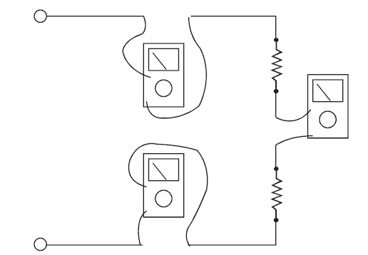
Figure 6: Ammeter connections to measure the same current at different points in a circuit
- Turn the circuit power back on.
- View the reading on the display unit. Be sure to note the unit of measurement.
- Switch power off again, once again proving with the T3 method while wearing your PPE.
- Disconnect meter leads from the circuit.
- If testing is finished at this test point, restore the circuit by reclosing the connection. When current measurements are complete, turn the function switch to the “OFF” position and remove the test leads.
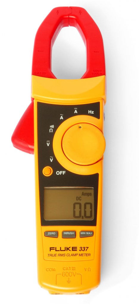
When measuring current on circuits with voltage values greater than 30 V or where “breaking” the circuit is impractical or dangerous, a clamp-on ammeter or amprobe can be used. These ammeters have two spring-loaded expandable jaws that allow you to clamp around a single conductor (Figure 7). This feature allows you to measure the magnetic field created by the current flowing through the wire to give an ampere reading without having to make physical contact or interfering with the circuit.
Figure 7: Clamp on Multimeter