Introduction to Resistance Measurements
You have studied voltage and current measurements, but you will find resistance measurements different in several ways. Resistance is measured with the circuit’s power turned off. The ohmmeter sends its own current through the unknown resistance and then measures that current to provide a resistance value readout.
Role of the Battery
Even though it reads out resistance, the ohmmeter is still a current-measuring device at heart. The ohmmeter is created from a DC current meter by the addition of a group of resistors (called multiplier resistors) and an internal battery. The battery supplies the current flow that is eventually measured by the meter. For this reason, use an ohmmeter only on de-energized circuits.
In the process of measuring resistance, the test leads are inserted in the meter jacks. The leads are then attached to the ends of whatever resistance is to be measured. Since current can flow either way through a pure resistance, there is no polarity requirement for attaching the meter leads. The meter’s battery sends a current flow through the unknown resistance, the meter’s internal resistors, and the current meter.
The ohmmeter is designed so that it will display 0 Ω when the test leads are clipped together (zero external resistance). The meter reads infinite (I) resistance or over limit (OL) resistance when the leads are left open. When a resistance is placed between the leads, the readout increases according to how much current that resistance allows to flow.
To conserve its battery, an ohmmeter should never be left on the ohms function when not in use. Since the current available from the meter depends on the state of charge of the battery, the DMM should be zero adjusted to start. This may require no more than a test of touching the two probes together.
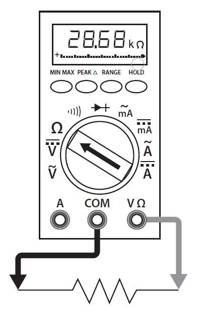
Figure 8 shows how resistance measurements are taken.
1000 Ω = 1 kΩ
1 000 000 Ω = 1 MΩ
Figure 8: Using a DMM to Measure Resistance
- Turn off power to circuit.
- Plug the black test lead into the common input jack. Plug the red or yellow lead into the resistance input jack.
- Select the resistance setting.
- Touch the probe tips across the component or portion of the circuit.
- View the reading and note the unit of measurement, ohms, kilohms, or megohms.
Resistance Measurement Procedures
Follow the steps below to measure resistance:
- Before testing begins the technician should always know what reading to expect based on the manufactures specifications, name plate rating, Ohms’s law and Kirchhoffs law. Testing blindly is dangerous and counterproductive.
- Turn off the power and prove the circuit to be measured is “dead” using the T3 testing method and the voltage measuring procedures. Be sure to wear your PPE as we always assume a circuit is “live” until proven otherwise
- Remove or isolate the component to be tested.
- Plug the test probes into the appropriate probe jacks, Common and Ω. Note that the jacks used may be the same ones used to measure volts.
- Select the ohms function by turning the function switch to ohms. Start with the lowest setting.
- Touch the probes together to check the leads, connections and battery life. The meter should display zero or a very small amount of resistance for the test leads. With the leads apart, the meter should display OL or I, depending on the manufacturer.
- Connect the tips of the probes across the break in the component or portion of the circuit for which you want to determine resistance. If you get an OL (over limit), switch to the next highest setting.
- View the reading on the display unit. Be sure to note the unit of measurement.
- Turn the meter off when testing is complete to prolong battery life.
