Digital Multimeters
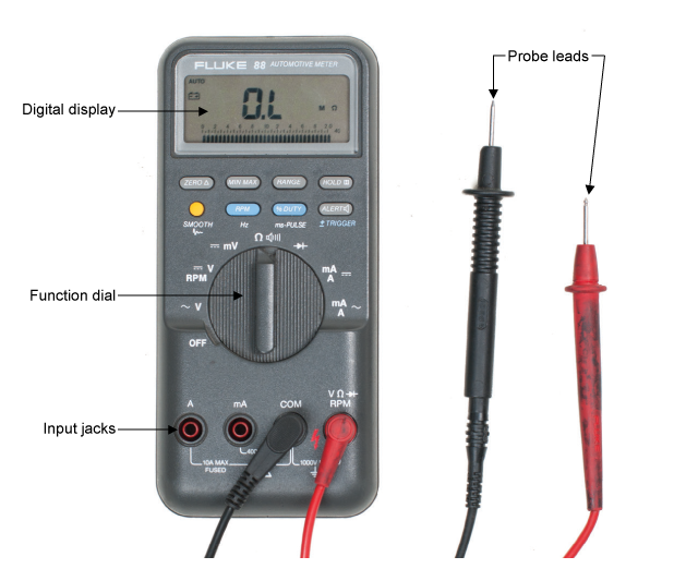
All digital multimeters combine the features of an ammeter, a voltmeter, and an ohmmeter. Figure 1 shows a typical DMM, although different makes and models may have a different number of digits in the display unit and the input/output jacks may be in slightly different positions. Since a DMM is an important tool, you will want to learn how to use one correctly.
Figure 2 – Typical Digital Multimeter

The upper portion of the DMM houses the display unit. The middle portion of the DMM houses the function switch, and the bottom portion contains the jacks for test leads.
The function switch normally has positions that will allow a technician to measure:
- AC/DC Volts (V)
- AC/DC Amps (A)
- Resistance Ohms (Ω)
In addition, some DMMs have function switch positions that will allow a technician to measure and to test diodes and capacitors. Some DMMs require manual setting of ranges; others have an auto ranging feature.
All DMMs may be used to measure voltage, current, and resistance. More advanced DMMs may measure frequency, relative power differences, or other important circuit parameters. Each measurement function has similarities and differences that you need to learn about.
Many meters will use symbols on the display, switch, and connections. Figure 2 lists some of the common symbols you may see.
Figure 2 – Common Symbols
| |
AC |
| |
DC |
| Ω | Ohms |
| |
AC or DC |
| Hz | Hertz |
| + | Positive |
| – | Negative |
| µF | MicroFarad |
| m | Milli |
| M | mega |
| Low battery | |
| Manual range or automatic touch hold | |
| Continuity beeper | |
| Diode | |
| Ground | |
| Fuse | |
| Double insulation | |
| Capacitor | |
| OL | Overload |

