Part 6 – Compressed Air Systems
Compressed Air Systems

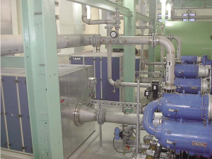
Ancillary Equipment:
Compressed air systems usually have 3 parts.
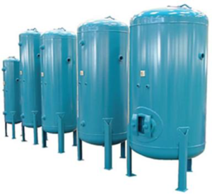
1) Receiver
|
2) Filter
|
3) Control Panel
|
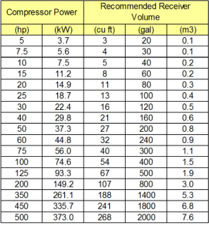
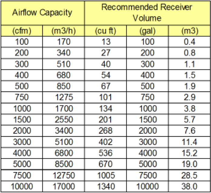
The Air Receiver size is determined according to 3 things: Compressor capacity, Regulation system, and Consumer’s air requirement.
 |
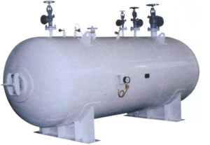 |
The Air receiver installation is a multistep process.
It begins by placing as near the compressor as possible to keep the discharge line short.
NOTE: The shut off valve should never be placed in this line unless a safety valve is installed between the valve and the compressor.
With several compressors feeding a main line, a safety valve must be fitted between the compressor and the first shut-off valve in the main.
The drain valve functions to drain moisture and oil. A trap is installed to drain condensed moisture and entrained oil carried over from the aftercooler. A pressure gauge is installed which indicates the air pressure in the receiver. Finally, a safety valve on the receiver is installed.

There are in principal two different air receivers in a compressed air system. Let’s take a look at each one and the differences between the 2 types.
1. Primary Receiver
This receiver is located near the compressor, after the after-cooler but before filtration and drying equipment
2. Secondary Receiver
This receiver is located close to points of larger intermittent air consumptions.
Take a look at the charts with the Compressor Power and Airflow Capacity and the recommended Receiver Volume (cu ft, gal, m3).
The maximum capacity of an air compressor always pumps more air than the system can use. Therefore a compressor must modulate its capacity during normal work. Simple controls cause more pressure variations in compressed air systems than more advanced strategies. In shorter periods the demand for compressed air may even exceed the maximum capacity of the compressor. What is common in well designed systems is not to design the compressor for the maximum peak loads.
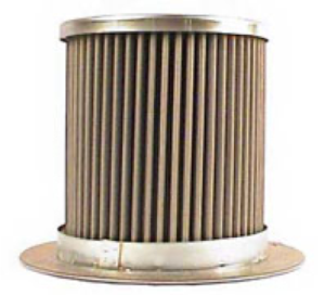
Suction filters have air that contains very fine particles of dust, sand and grit. Concentrations of suspended solids range from 100 mg to 1100 mg per 100 m3 of air.
Intake Filter
Separators
Lubricated compressors are structured so that air/oil separator is installed after the compressor to remove the lubricant injected into the compressor.
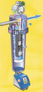
- Economizer differential pressure gauge
- Three-piece aluminum housing
- Low pressure drop flow channel
- O-ring housing seal
- Double O-ring Element seal
- Built-in acoustic alarm
- Tapered bowl
- Selection of pre-and afterfilter elements
- Ultramat zero air-loss condensate drain valve
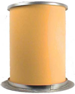
Air Filtration
Separators
Let’s look at the different types of separators.

Conventional Wrap Style Air/Oil Separators
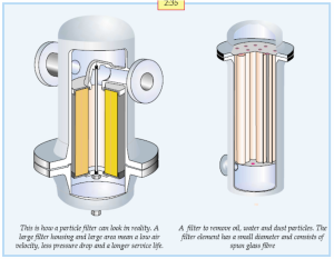
Most wrap-style oil separators are glass fiber elements with a consistent pore size. The wrap style oil separator was the original design to remove oil aerosols from compressed air streams. In general, a pleated or deep air oil separator retrofit will add service life and reduce oil carryover.
Pleated Air/Oil Separators
A filter pleat that looks a little like a wave is added to the air-oil separators media during manufacturer. Pleated filter media increases the air-oil separators capacity. Pleated oil separators can handle on average two times the air flow of a conventional air-oil separator.
Deep Filter Air Oil Separators
Deep filter air/oil separators have several grades of glass fiber filter media wrapped on them. The benefit of a deep filter separator is increased air flow capacity similar to a pleated separator, while maintaining a low initial pressure drop and residual oil content. These separators can handle more oil aerosol than a conventional or pleated separator
Spin-on Air-Oil Separators
Typically a spin-on air-oil separator is a deep style air-oil separator placed inside a spin-on filter can. Spin-on Air-Oil Separators are extremely easy to change-out but are limited in application because of air flow capacity restrictions.
Refrigeration and Natural Gas Air-Oil Separators
Special materials of construction are used in these oil separators to ensure chemical compatibility with gases including freon, ammonia, and natural gas. These gases and other material often present in natural gas are not compatible with standard air/oil separators, therefore the need for special refrigeration and natural gas air-oil separators.
| Cause | Effect | Solution |
| Liquid water entering refrigerated air dryer. | Inefficient dryer operation leading to higher cost and/or inability to meet dew point.
|
Intall water sepererator after air compressor and coalescing prefilter before air dryer.
|
| Liquid water entering regenerative desiccant air dryer. | Inability to meet dew point. Damage to dryer componens such as valves and/or desiccant.
|
Install water seperator after air compressor and coalescing prefilter before air dryer.
|
| Hydrocarbon and/or oil vapors entering process airstream.
|
Product spoilage. Odor and/or taste in process air.
|
Install high AK carbon filter after air dryer. |
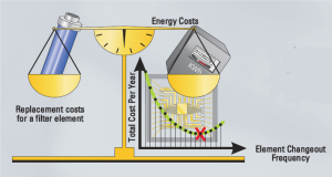
| High pressure drop across filters. | Increased energy consumption to maintain pressure. Low line pressure leading to inefficient operation of downstream equipment. | Install filters with housings and elements engineered for low pressure drop. Replace elements at optimum point to keep both maintenance and energy costs at a minimum. |

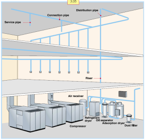
Air Distribution
Air Quality Summary
Power Air: Refrigerated compressed air dryer and particulate filter are required
Used for:
- Air tools
- Sand blasting
- Pneumatic control components
Instrument Air:
Used in:
- Pneumatic process control systems
- Powder coating
- Paint spraying
- Climate control systems
- Packing machines
Process Air
- Refrigerated compressed air dryer, oil removal filter and oil vapor absorber may be required
Breathing Air: Aftercooler, coarse pre-filter, and auto draining water trap required suitable in-line sorbent beds and filters required. Breath air quality is used in hospital air systems, diving, cleaning of breathing equipment.
Activity: Diagram of an Air Compression System
Click on the “+” spots to reveal parts of an air compression system.