Part 1 – Refrigeration Codes and Standards
The primary refrigeration code standard in Canada is CSA B52-99, Mechanical Refrigeration Code. The recommended code only – does not have the force of law until it is adopted by a jurisdiction, usually a province.
Additional codes and standards are:
- ASME (American Society of Mechanical Engineers),
- ASHRAE (American Society of Heating, Refrigerating and Air-Conditioning Engineers)
- ANSI (American National Standards Institute)
- ISO (International Standards Organization)
The following sections summarize what is contained in the code CSA B52-99. Consult the original code as applied within a specific jurisdiction before making a decision on design, construction, installation, or maintenance.
Section 1:
Note the types of equipment it applies to and the types of equipment excluded. The use of water or air as a refrigerant is also excluded.
1. Scope
1.1 Purpose
- The purpose of this code is to provide minimum requirements for the design, construction, installation, and maintenance of those mechanical refrigeration systems included in Clause 1.2, so as to minimize the risk of human injury.
- Note: This code does not directly address the protection of property and preservation of the environment, which may be addressed in other Acts, Regulations, Codes, and Standards.
1.2 General
1.2.1 Design, Construction, Installation, Inspection, and Maintenance
- Except as provided for in Clause 1.2.2, this code applies to the design, construction, installation, inspection, and maintenance of every refrigeration system, as provided for by the Act and defined in this Code.
1.2.2 Exemptions
- This code does not apply to the use of water or air as a refrigerant, nor to bulk-storage gas tanks that are not permanently connected to a refrigeration system, nor to refrigeration systems installed on railroad cars, motor vehicles, motor-drawn vehicles, aircraft, or ships, nor to refrigeration systems used for air-conditioning systems in private residences, unless otherwise provided for by the Act.
1.2.3 Application Criteria
This code applies to:
a. All refrigeration systems installed subsequent to its adoption. This includes refrigeration systems installed in new or existing premises. It also applies to all premises, including the machinery room, if required, in which a refrigeration system is to be installed.
b. Refrigeration systems that undergo a substitution of refrigerant. This includes the requirements on premises as noted in Item (a).
c. Those parts of a refrigeration system that are replaced in, or added to, refrigeration systems installed prior to its adoption.
- Note: When adding or replacing parts (see Item (c)), consideration should be given to the requirements on premises as noted in Item (a).
1.2.4 Unit of Measurement
- The values given in SI (metric) units are the standard. The values given in parentheses are for information only. Conversion factors are provided in Appendix D.
Section 2: Reference Publications and Definitions
This section lists relevant publications, including other CSA standards and standards from ASME, ANSI and ASHRAE. This is followed by a list of terms and their definitions.
Section 3: System Selection and Application Requirements
An application procedure is outlined in this section based on the following criteria:
- Occupancy: this is a classification of the location of the refrigeration system based upon occupancy. It is divided into residential, commercial, industrial and mixed occupancy.
- Type of refrigeration system:
- Direct: The evaporator or condenser is in direct contact with the air or other substance to be cooled or heated
- Double direct: Two refrigerant systems connected with the primary circuit directly cooling the substance, such as a cascade system
- Indirect: A secondary coolant loop is used to cool the substance
- Along with this classification is one that deals with the leakage probability or the likelihood that a leakage of refrigerant could enter an occupied area.
- Classifications of Refrigerant: Refrigerants are classified into safety groups according to their flammability and toxicity using a matrix developed by ANSI/ASHRAE Standard 34.
Section 4: Equipment Design and Construction
Drawings, Specifications, and Data Reports
Drawings and Specifications
- Mentions that all pressure vessels and associated piping and fittings must adhere to the most current edition of CSA B51, Boiler, Pressure Vessel and Piping Code.
- This code specifies all requirements for submitting drawings and specifications to the regulatory authority for approval.
Refrigeration Systems Under 125 kW
- Refrigeration systems under 125 kW, i.e., household refrigerators, dehumidifiers, and room air conditioners, are covered by specific CSA Standards that require testing and certification by approved testing laboratories.
Refrigeration Systems Over 125 kW
- For all refrigeration systems higher than 125 kW, drawings and specifications must be submitted to the regulatory authority for registration and acceptance.
Material Selection
- The types of materials that may be used are described.
- Copper may not be used for ammonia refrigerant.
- Aluminum and its alloys are deemed to be suitable for ammonia.
- Aluminum, zinc, magnesium, and their alloys are not to be used with methyl chloride.
Refrigerant-Containing Components
Requirements for Refrigerant-Containing Pressure Vessels, Piping, Fittings, and Other Components
- This section deals with the requirements for stop valves so that the refrigerant can be handled for servicing purposes without venting to the atmosphere.
- Covers marking and labeling requirements and includes instructions on the substitution of refrigerant type.
Pressure Testing
Factory Testing
- Design pressures shall not be less than the pressures expected under all operating, shipping, and standby conditions.
- An extensive table of minimum design pressures is given for refrigerants in common use.
- For factory testing, the test pressure needs to be at least 1.25 times the design pressure of the component with the lowest design pressure (for both the high side and the low side).
Field Testing
- Field testing is dependent not only on the design pressure, but also on the setting of the pressure relief valves.
Section 5: Installation
Machinery Room Requirements
General instructions deal with foundations and supports and access for servicing.
Machinery room requirements include:
- Access (doors and security) to machinery rooms
- Requirement for a refrigerant vapour detector
- Explosion protection
- Ventilation (natural or mechanical)
- A special Class T machinery room, with additional safety measures. Defined for cases where the amount of refrigerant exceeds specified quantities and could be hazardous to occupants.
Other topics covered are:
- Electrical requirements for ammonia systems
- Location of refrigeration piping and refrigeration parts
- Joints in air ducting.
Section 6: Overpressure Protection
Specifies requirements for providing pressure-relief devices for pressure vessels.
Pressure-Relief Devices for Pressure Vessels
Pressure Vessels with Volumes Less than 0.085 m3 (3 ft3)
- Pressure vessels, with volumes less than 0.085 m3 (3 ft3), need pressure-relief devices or fusible plugs, unless the diameter is less than 152 mm (6 in).
Pressure Vessels with Volumes Greater than 0.085 m3
- For volumes greater than 0.085 m3, various rules apply for pressure-relief devices, and sometimes a second pressure-relief device is required.
Pressure-Relief Device Operation
Prevention of Pressure Exceeding 10%
- The pressure-relief device must prevent the pressure from rising more than 10% above the setting of the pressure-relief valve.
Pressure-Limiting Devices
- Pressure-limiting devices are generally needed if there is more than 10 kg of refrigerant.
Protection Mechanisms
- Devices protect against overpressuring caused by the compressor, expansion of liquid refrigerants, and other causes.
- A calculation is provided for the required discharge capacity, along with tables for the length of discharge piping allowed after the pressure relief valve.
Section 7: Maintenance of Systems
- Servicing of refrigerants, including both withdrawal into suitable containers and storage.
- Other maintenance requirements include:
- Replacement or recertification of pressure-relief devices at least every five years.
- Annual testing of pressure-limiting and other safety devices.
- Testing leak detectors.
- Any safety-related maintenance recommended by manufacturers.
- Annual checking of electrical connections.
- Periodic refrigerant leak testing.
Section 8: Precautions
- The owner of the refrigeration system must provide personal protective equipment for its employees as required by the jurisdiction.
- Enclosed spaces that contain refrigeration equipment must have doors that can be opened from the inside and either a second door or an alarm system that can be operated from inside the space.
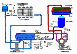
Direct and Indirect Cooling Systems
Direct cooling is evaporating coils are placed directly in the rooms to be cooled. Liquid refrigerant is evaporated in them without the intervention of brine or any other carrying medium.
Indirect cooling is evaporating coils are lead through a tank containing a liquid i.e., brine, water, etc. Ammonia, in evaporating, extracts heat from and cools the brine. Brine is then pumped through the cold rooms and carries heat from these rooms back to the evaporator.
The advantages of Indirect System:
- Keep a more even temperature in the cooling rooms than direct systems.
- Not the same danger of spoiling foods in storage with a brine leak, as there would be with an ammonia leak in the direct system
- Has a slightly lower operating cost for small or medium-size plants.
- The direct system has the advantage in very large plants.
The Disadvantages of the indirect system:
- The indirect cooling system requires the addition of a brine tank and brine circulating pump
- There are two transfers of heat (from room to brine and from brine to ammonia), while there is only one transfer of heat (from the room to the ammonia) in the direct system
- A larger quantity of refrigerant is required for charging the plant
- A brine tank or brine pump is needed for the indirect system
- More expansion valves are required since each bank of cooling coils must have its own regulating valve.
- The condenser and compressor construction and operation are the same whether the cooling is carried out directly or indirectly.