Part 8 – DC Motor Starters
DC Motor Starters
At the moment a DC motor is started the armature is stationary therefore no counter EMF is being generated. The only component that limits the starting current is the armature resistance. In most DC motors the armature resistance is a very low value (approximately one ohm or less). In order to reduce this very high starting current, an external resistance must be placed in series with the armature during the starting period.
For example, a 10-hp motor with an armature resistance of 0.4 ohms, if supplied by a 260 VDC source, would result in a current of 650 amps, which is approximately twelve times greater than its actual full-load current. Such high current levels can cause severe damage to the brushes, commutator, or windings. Therefore, starting resistors are typically incorporated into the motor design to limit the starting current to 125 to 200 percent of the full load current.
Automatic starting of DC motors offers several advantages over manual control, including the ability to arrange settings on the starter for uniform acceleration throughout the motor run-up, while simultaneously eliminating the chances of improper operation that may occur under manual control.
There are three types of automatic starters:
- Counter-E
- Current limit
- Time limit
Counter-E Starter
Counter-e staters have voltage-sensitive relays. They sense armature voltage and disconnect the armature resistance in steps as the motor counter EMF builds up.
Activity: Counter-E Starter
Click the tick marks on the slider to learn more about the counter-e DC motor starter.
Current Limit Starters
Current limit starters measure the armature current flow and adjust the circuit’s resistance as the starting current decreases. This method offers the advantage of enabling the motor to start quickly under light load conditions and more slowly when dealing with heavy loads.
Activity: Current Limit DC Motor Starter
Click the tick marks on the slider to learn more about the current limit DC motor starter.
Time Limit
Time limit compound motor starters operate through definite time lag relays, strictly operating on a time basis and cutting out armature resistance steps at definite time intervals.
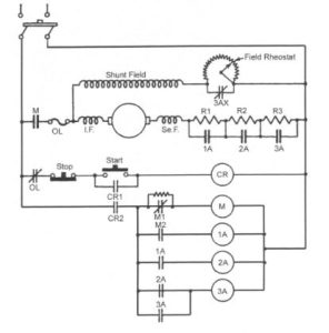
DC Motor Starters
The contactors 1A, 2A, and 3A have time-closing contacts which are energized in sequence beginning with the main contactor M (operating auxiliary contacts M2).
When all have closed and have cut out the armature resistances R1, R2, and R3 (normally closed), contacts 3AX are opened and the final motor speed adjustment and control is carried out by variation of the field rheostat resistance in the shunt field. The motor is stopped in the same way as in the counter-emf and current-limit starters
The sequence is repeated until all armature resistance is cut out, the motor then runs at standard speed until either stopped by hand or tripped on overload.