Part 1 – Fuse and Circuit Breakers (Electrical Systems Protection)
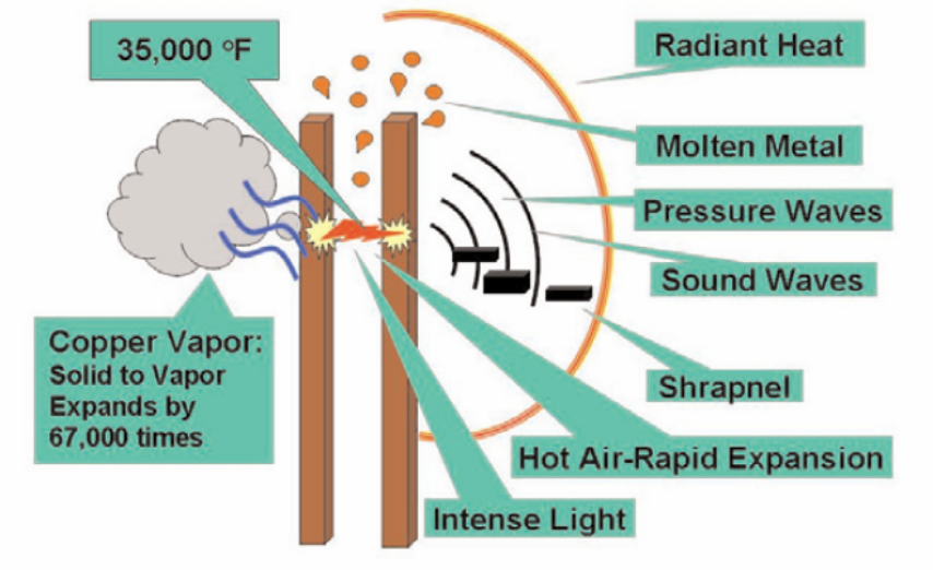
Electric Arc
Safety
Electrical Codes regulate installation of equipment and that there must be protection from overcurrent. Fuses, circuit breakers, and protective relays provide such protection.
Purpose
-
- Minimize damage
- Leave unaffected equipment in-service
- Maintain equipment operating limits
- Maintain electrical system stability
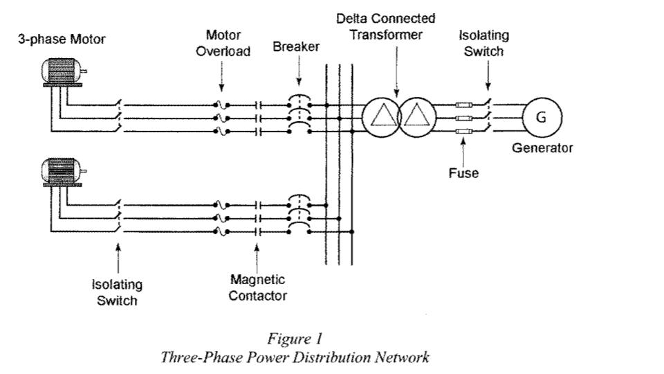
Example: Three-phased Power Distribution Network
Breakers and Fuses
Protect against two types of faults:
- Overcurrent (overload)
- Short-circuit current
Overcurrent (overload)
Operation of conductors or equipment at a level that will cause damage if allowed to persist. This type of fault does not leave the normal current path of the circuit. Larger than intended electric current runs through a conductor, leading to excessive generation of heat, and the risk of fire or damage to equipment.
Short circuit
Current flow is shorted, so, it doesn’t run through the load. Bypasses the load resistance that limits the current value. Does not mean a circuit with zero resistance. Arc welding is a common example of the practical application of the heating due to a short circuit.
A short circuit can occur between one of the phases and ground, between two of the phases, or among all three phases. Breakers or fuses automatically interrupt the current. Both must have capacity to interrupt the amount of short circuit current that is available in the power distribution system.
There are several important considerations for proper fuse selection:
- Normal operating current
- Overload current and time interval in which the fuse must open.
- Application voltage (AC or DC Voltage).
- Inrush currents, surge currents, pulses, start-up currents characteristics.
- Ambient temperature.
- Applicable standards agency required, such as UL, CSA, VDE.
Other considerations include:
- Reduce installation cost
- Ease of removal
- Mounting type/form factor, etc.
There are two basic ratings for fuses:
- Continuous Current Rating
- Maximum Voltage rating
Continuous Rating
Continuous rating of a breaker or fuse refers to its ability to continuously carry a certain amount of current. Electrical codes state that a breaker may only be applied to 80% of its continuous rating. A breaker with a continuous rating of 200A would not be installed to protect a circuit that draws 250 A, called “underrated”.
Available fuses for a circuit may be designed in increments of 70 A, 80 A, 100 A and 125 A. The full-load current for a circuit is calculated to be 84.4 A:
- 100 A breaker would be rated for 80 A – underrated.
- A 125 A breaker would be used in this example
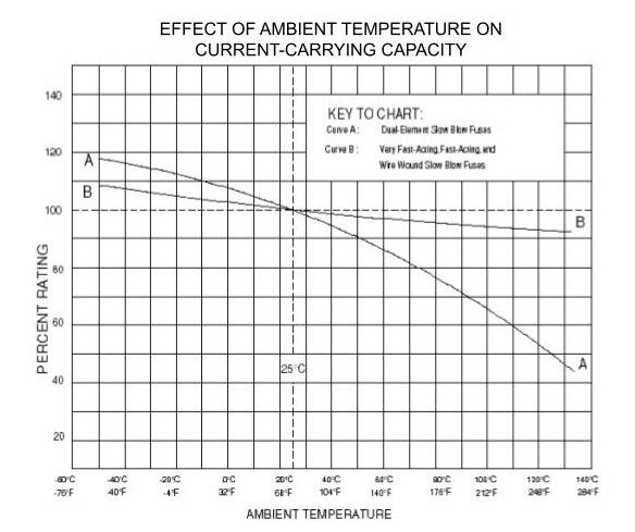
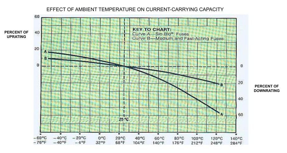
The continuous rating is affected by temperature. Current carrying capacity tests of fuses are performed at 25C and are affected by changes in ambient temperature. Fuse ambient temperature is significantly higher because it is enclosed or mounted near other heat producing components.
Example: Effect of Ambient Temperature on Current-Carrying Capacity
For example, a breaker may have a continuous rating of 100 A at 40 °C. Continuous rating would have to be derated if the breaker was installed at an ambient temperature of 50 °C.
Maximum Voltage
Breakers and fuses are also rated according to the maximum voltage they can handle. A fuse rated for 250 V service could not be installed in a 600 V circuit.
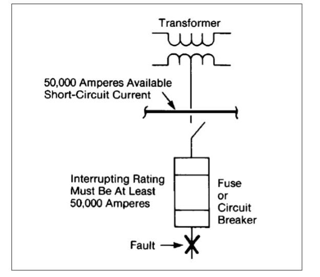
Interrupting Capacity
Capability of a breaker or a fuse to safely open an electrical circuit that is carrying a dangerous amount of current. This capacity is rated in root mean square (rms) A. A fuse used on a high voltage installation may have an interrupting capacity of 100,000 A. A different type of fuse used on a lower voltage installation may have an interrupting capacity of 10,000 A.
Inverse Time Principle
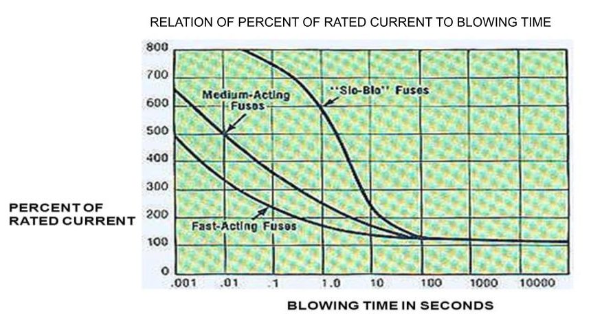
Breakers and fuses operate based on an inverse time/current principle. Greater the current flow, the faster the protective device will need to operate to clear the overcurrent fault or short circuit current. A breaker may clear a 10,000 A fault in 10 milliseconds.
The clearing time of a 32 A fuse if the circuit is drawing:
450 A 🡺 0.01 seconds
100 A 🡺 4.0 seconds
40 A 🡺 several thousand seconds
32 A or less 🡺 Fuse will not blow
Example: Relation of Percent of Rated Current to Blowing Time
Fuses
An overcurrent protective device that contains a calibrated current carrying element that melts and opens a circuit under specified overcurrent conditions.