Part 7 – Power in AC Circuits
Power
True Power
The power (watts) that is actually used in the circuit. Power is associated with the total resistance in the circuit. The actual power that is converted into another form of energy by the circuit is measured with a wattmeter.
Calculated using the following formula:

Where:
- P = True Power (Watts)
- I = Resistive Current (Amperes)
- R = Resistance (Ohms)
- E = Circuit Voltage (volts)
Reactive Power
Reactive power does not produce an energy conversion in the circuit. It is measured in Volt-Amperes Reactive (vars). The reactive loads such as inductors and capacitors dissipate zero power because they drop voltage and draw current giving the impression that they actually do dissipate power.
Reactive power is calculated using the following formula:

Where:
- Q = Reactive power (Volt-Amps-Reactive (VAR))
- I = Impedance (amps)
- X = Reactance (ohms)
- E = Circuit Voltage (volts)
Apparent Power
Power that appears to the source because of the circuit’s impedance. It is the power that the voltage sees. When meters are used to measure power in an AC circuit, apparent power is the voltage reading multiplied by the current reading. The combination of true power and reactive power.
Apparent power is calculated using the following formula:
S = I2Z
= E2Z
= IE
Where:
- S = Apparent power (Volt-amperes (VA))
- I = Current (amps)
- Z = Impedance (ohms)
or
Apparent power = √((True power)2 + (Reactive power)2)
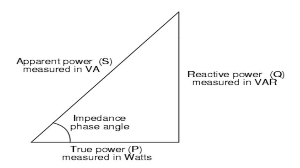
Power Triangle
A power triangle is a graphical representation used to depict the relationships between real power (measured in watts), reactive power (measured in volt-amperes reactive or VAR), and apparent power (measured in volt-amperes or VA) in an alternating current (AC) circuit. It helps to illustrate how these three quantities are related and how they contribute to the overall power in the circuit.
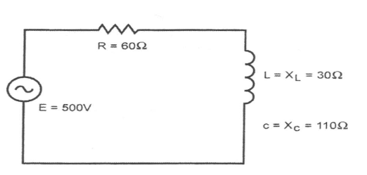
Example:
The circuit shown below has a supplied voltage of 500V, resistance of 60 ohms, inductance of 30 ohms, and capacitance of 110 ohms.
Calculate the following:
a) True power
b) Apparent power
Solution:
- R = 60 ohms
- XL = 30 ohms
- XC = 110 ohms
- E = 500 volts
a) True Power
XT = XC – XL
= 110 – 30
= 80 Ω
Z = √(R2 + XT2)
= √(602 + 802)
= √(3600 + 6400)
= √(10000)
= 100 Ω
IZ = E/Z
= 500/100
= 5 A
True Power = I2R
= 52 x 60
= 25 x 60
= 1500 watts
= (5)2 x 100
= 25 x 100
= 2500 VA
Solution
- R = 60 ohms
- X = 80 ohms
- Z = 100 ohms
- E = 500 volts
- I = 5 amps
True Power = 1500 watts
b) Apparent Power
Apparent Power = I2Z
= (5)2 x 100
= 25 x 100
= 2500 VA
Alternate Solution:
- R = 60 ohms
- X = 80 ohms
- Z = 100 ohms
- E = 500 volts
- I = 5 amps
True Power = 1500 watts
b) Apparent Power
Reactive Power = I2X
= (5)2 x 80
= 2000 vars
Apparent Power = √((True Power)2 + (Reactive Power)2)
= √((1500)2 + (2000)2)
= √(625 x 104)
= 2500 VA