Part 7 – DC Motors
DC Motors
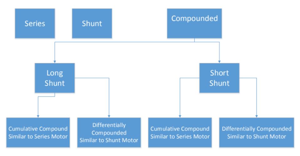
Three Basic Types of DC Motors (Series, Shunt, Compounded)
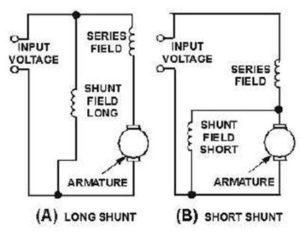
2 subcategories of Compounded Motors (Long Shunt/Short Shunt)
2 subcategories of cumulative and differentially compounded
There are three basic types of DC Motor:
- Shunt
- Series
- Compound
Shunt Motor
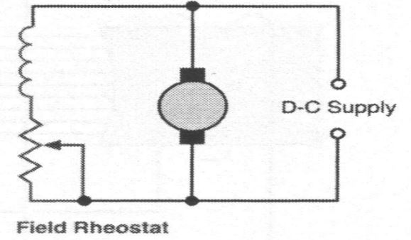
Shunt motors are the most common type of DC motor. They are connected similarly to shunt generators, the field winding is linked in parallel with the armature winding across the power supply line, allowing the field current to remain constant, while the armature circuit can be utilized to control the motor. Typically, a field rheostat is connected in series with the field.
The current in the shunt field winding differs from the armature current. Shunt field windings create the essential magnetic field using many turns of thin, high-resistance wire, resulting in a relatively small shunt field current compared to the armature current.
Shunt MotorA shunt motor offers good speed regulation and is classified as a constant-speed motor, despite a slight decrease in speed when the load increases.
Activity: Shunt Motor
Click the arrows to learn more about shunt motors.
Speed Control
Rheostat is used in series with:
- Field winding
- Armature winding
- Both
Activity: Field Winding Speed Control
Click the accordion to learn more about field winding speed control.
Activity: Armature Winding Speed Control
Click the accordion to learn more about armature winding speed control.
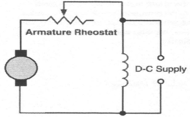
The most common and preferred method is placing a rheostat in series with the field winding rather than using an armature rheostat. This is because the field current is lower than the armature current, resulting in reduced power loss across the rheostat and making more current available for motor operation.
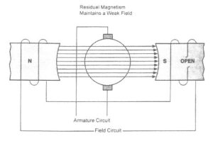
When the field winding is disconnected in a shunt motor, it tends to keep running instead of coming to a stop. This happens due to the lingering magnetic field in the pole pieces, which results from residual magnetism. It’s worth noting that the armature circuit can continue to draw current in this scenario, as both the field winding and the armature are connected in parallel to the power supply.
Activity: The Shunt Motor Open Field
Complete the activity below to learn more about the shunt motor open field.
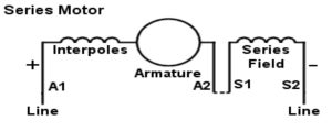
Series Motor
In a series motor, the field is connected in series with the armature, resulting in the field winding having only a few turns of relatively large wire. This design mandates the field winding to carry the full armature current, and any alterations in the load lead to adjustments in both the armature current and the field flux. Consequently, as the load varies, the motor’s speed also changes accordingly.
Series motors are known for their exceptional ability to generate substantial torque when starting from a standstill. They are commonly employed in various applications such as small electric appliances, portable electric tools, cranes, winches, and hoists. However, it’s important to note that the speed of a series motor can vary significantly between no-load and full-load conditions, making it unsuitable for situations where a relatively constant speed is needed in the presence of varying loads.
In a series motor:
Increase in load current 🡺 increase in field flux.
- Increase in field flux 🡺 decrease in speed.
Decrease in load current 🡺 decrease in field flux.
- Decrease in field flux 🡺 increase in speed.
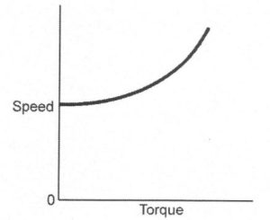
Torque and speed are inversely proportional.
- When the torque is low, the speed is high.
- When the torque is high, the speed is low.
Activity: Series Motor
Click the image hotspots to learn more about series motor.
A series motor started or run without a load has a tendency to “run away.”
- With no load, a low torque is required to turn the armature.
- Motor speeds up in an attempt to increase CEMF to reduce the armature current and torque.
- As the motor runs faster to reduce the armature current, the field flux and CEMF also drop.
- The motor runs faster to build up more CEMF.
- Speed continues to increase until the physical force of rotation damages the motor.
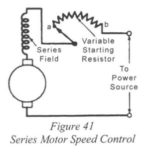
Speed Control
Inserting resistance in the armature circuit controls the speed of a series motor.
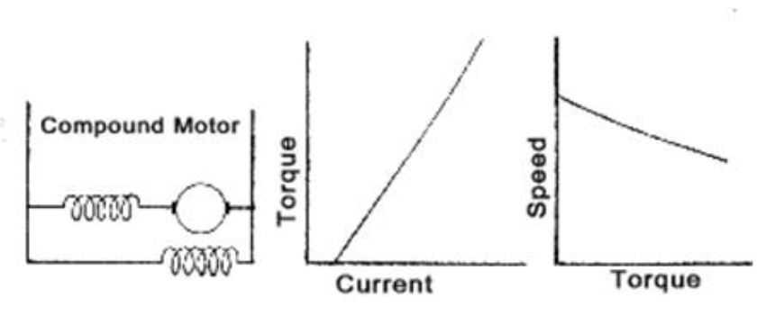
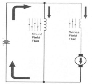
Compound Motor
A compound motor has both a shunt field and a series field.
Activity: Compound Motor
Click the image hotspots to learn about compound motors.
There are two types of compound motors:
- Cumulative compound
- Differential compound
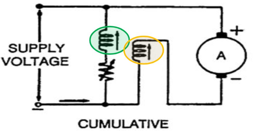
Cumulative Compound Motor
Cumulative compound motors feature a shunt field winding and a series field winding that are wound in the same direction. These windings work together to generate the necessary magnetic flux. Essentially, they combine a series motor with a small number of shunt turns to prevent the motor from running uncontrollably in no-load situations.
In a cumulative compound motor, there is a distinct no-load speed, and it can be safely operated under such conditions. However, when it comes to speed regulation, cumulative compound motors are not as effective as shunt motors. This is because the addition of a load causes a more significant decrease in speed due to the increase in flux in cumulative compound motors compared to shunt motors.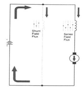
A cumulative compound motor delivers greater torque compared to a shunt motor with the same armature current because of the enhanced flux provided by the series field winding. These motors are commonly employed in applications where a relatively consistent speed is needed, even with irregular loads, especially in reciprocating machinery like presses and shears. Some cumulative-compound motors incorporate a series winding to provide high starting torque for motor initiation. After reaching its standard running speed, this series winding can be disconnected using a switch, allowing the motor to operate based on the speed-regulating attributes of a shunt motor.
A small shunt winding adds supplementary flux to the primary series flux, providing the motor with the high torque characteristics of a series motor. Importantly, this design prevents the motor from running uncontrollably under no-load conditions due to the shunt characteristic it exhibits.
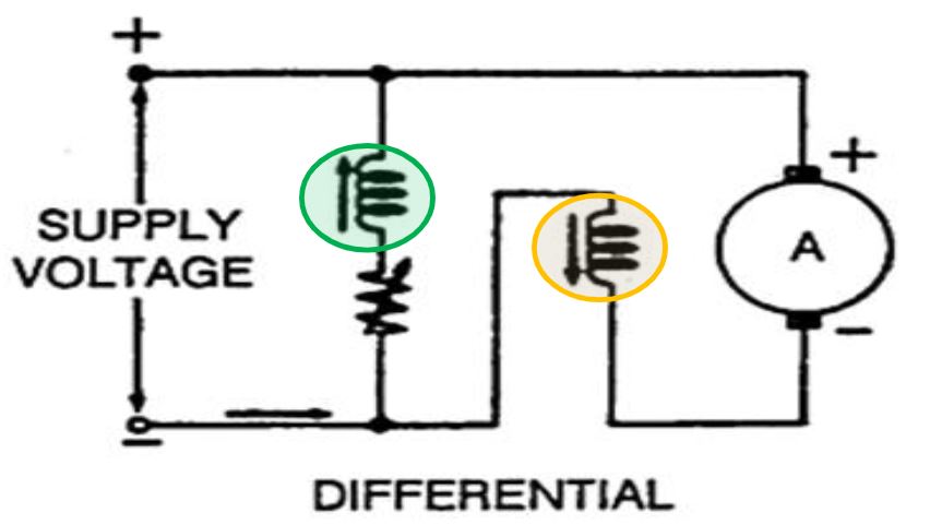
Differential-Compound Motor
A shunt motor with a small series field winding. Field windings are wound in opposite directions so that the series field subtracts from the shunt field. They operate at a constant speed under varying load conditions and give better constant speed regulation than the standard shunt motor. Shunt motors do not have good starting torque because the shunt field overrides the series field. The series field acts to make the motor more sensitive to load changes.
In a compound motor, when an increase in load leads to a slowdown, several key actions take place:
- The counter-electromotive force (CEMF) decreases, prompting more armature current to flow in an effort to boost motor speed.
- The current in the series field windings also increases.
- This surge in series field flux counters and diminishes the prevailing shunt field flux.
- The reduction in field strength results in the motor speeding up to re-establish the CEMF.
- This dynamic response enables the motor to react swiftly and maintain its speed effectively.
Differential compound motors maintain a nearly consistent speed across various loads, but they exhibit inadequate torque performance under heavy loads. Consequently, they are rarely employed in practical applications.
Activity: DC Motors
Complete the activity below to learn more about DC motors.
Activity: Series Motors
Complete the activity below to learn more about series motors.
Activity: Reversing DC Motors
Complete the activity below to learn more about reversing DC motors.
Activity: DC Compound Motors
Complete the activity below to learn more about DC compound motors.