Part 2 – Transformer Rating
There are four factors that affect transformer performance which are:
- Kilovolt amperes (kva) rating
- Impedance
- Temperature rise
- Harmonics
Kilovolt Amperes (kVA) Rating is the amount of current that the transformer can supply at a certain voltage.
A single-phase 10 kVA transformer operating with a secondary voltage of 240 volts can supply:
 =
= 

Kilovolt Amperes (kVA) Rating is a three-phase 112.5 kVA transformer operating with a secondary voltage of 208 volts can supply:
 =
= 

For transformers with auxiliary cooling fans, you have two ratings. One rating that applies when the fans are not operating and a second rating that applies when the fans are operating. The kVA rating of a transformer is stamped on the nameplate located on the transformer enclosure and large power transformers are often rated in Megavolt Amps (MVA) instead of kVA.
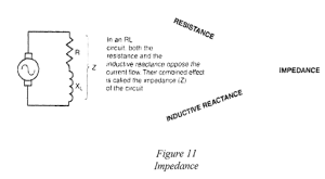
Impedance
Resistance in resistive circuits provides the only opposition to current flow and is unaffected by the circuit current or voltage. In inductive circuits, opposition is provided by inductance in the form of inductive reactance and inductive reactance is directly proportional to frequency. Its value depends on the frequency of the applied voltage.
The phase relationship between the current and the voltage drop is different for a resistance than it is for a reactance because voltage drop is a measure of the opposition to current, resistance and inductive reactance can be considered as differing in phase.
Transformer impedance short circuit had a tremendous amount of energy that could do significant damage. Transformers, conductors, and other equipment must be built to withstand this amount of energy. Lower transformer impedance means fewer losses but increases the amount of short circuit current available in a power distribution system. Protective devices such as breakers and fuses must be capable of operating quickly so that the amount of energy delivered to a short circuit is limited.
Video: Transformer Boom
Watch “Transformer Book” [0:24].
Transformer Short Circuit
Calculating Impedance and Short Circuit Value:
A 1000 kVA rated transformer with 480 secondary volts and 5.75% impedance has a rated full-load secondary amps of: 1,000,000 VA/(480 x √3) = 1203 amps
1203 amps will flow in the secondary if the secondary is short-circuited and the primary voltage is increased to a point where the secondary voltage is: 5.75% x 480 volts = 27.6 volts
Therefore, the impedance (Z) of the secondary windings is: Z = V/I
= 27.6 volts/1203 amps
= 0.02294 ohms
If there were a short circuit fault on the secondary side, the transformer would deliver: 480V/0.02294 ohms = 20,924 A
*1000 kVA = 1000 x 1000 VA/kVA = 1,000,000 VA
*The voltage required in the secondary winding to generate 1203 A. A function of independence.
Temperature Rise
Copper losses in the windings and magnetic losses in the core are converted into heat. Materials and the design of transformer cooling systems need to accommodate this temperature rise.
Increasing the diameter of the conductor lowers resistance of the windings, reduces copper losses, and reduces temperature rise.
Increasing the diameter of the winding means increasing the size of the core, increase of magnetic losses, and cost per unit will go up to achieve a lower temperature rise that increases in cost and may be offset by longer transformer life expectancy.
Temperature rise values indicate the maximum temperature rise (in degrees Celsius) that a transformer will exhibit at full-load conditions. Good indicator of transformer efficiency and general quality and an efficient transformer loses less power through heat and operates at a cooler temperature. Altitude reduces the ability of air to cool a transformer. If operated at higher altitudes, the kVA rating should be reduced 0.3% for each 100 m above 1000 m, depending on the manufacturer.
Harmonics
Harmonics are natural multiples of fundamental frequencies. In general, transformers used in power systems operate at a fundamental frequency of: 60 Hz in North America and 50 Hz in Europe and many other parts of the world. The third harmonic for a 60 Hz system has a frequency of: 3 x 60 = 180 Hz.
Non-Linear Loads
The switch mode power supplies in consumer electronics (computers and stereo systems) create harmonics that are disruptive to distribution transformers. Harmonics in transformers cause more losses, more heat, and less efficiency, and a rating factor called the K-factor is an indicator of how well a transformer tolerates harmonics.