Part 2 – Fuse Design
Fuses
Fuses fall into the following categories for low, medium and high voltage ratings.
- Low Voltage – 1,000V and below
- Medium Voltage – from 1,000V to 69,000V
- High Voltage – greater than 69,000V
Current Rating: Nominal amperage value of the device.
Rerating (Derating): The current rating of a fuse is typically derated 25% for operation at 25oC to avoid nuisance blowing. Example: a fuse with a current rating of 10A is not usually recommended for operation at more than 7.5A in a 25C ambient.
Activity: Click through the images showing fuse examples.
Video: Watch this footage of up to 1000 frames/second showing different fuses blowing in a broken DC power supply.
Characteristics refer to how rapidly it responds to various current overloads. The following are the basic types of fuses:
- Single-element fast-acting
- Dual-element time-delay
- Expulsion
- Current-limiting
Voltage Rating is the maximum voltage at which a fuse is designed to operate. Exceeding the voltage rating of a fuse impairs its ability to clear an overload or short circuit safely. Fuse can be used at any voltage below the fuse voltage rating. A 250V fuse can be used in 125V circuits. Voltage ratings are assumed to be for AC unless specifically labeled as DC.
Single-Element Fast-Acting Fuse is used for protection of circuits where little or no current surges such as inrush.
Cartridge fuses
Cartridge fuses consist of a cylindrical body and a fusible link. Circuit-opening fusible link is directly heated and destroyed by the passage of overload current through it. In some types of fuses, the fusible link is replaceable.
Activity: Click through the images below.
The body of the fuse has metal end ferrules that allow the fuse to be installed in fuse-holders. It has copper blades on the ferrules that are part of the installation assembly. On this particular fuse, one blade is notched so that a fuse with different characteristics cannot be installed in the same circuit. The continuity of the fuse element is determined with a metre. The illustration on the right in Fig. 5 shows a cartridge fuse with a glass body. This allows the fuse link to be viewed.
**Insert Figure 5**
In some fuses, the suppression of the arc (due to fuse blowing) is accelerated by filler material in the body of the fuse. Body of the fuse contains the arc and prevents damage that might occur from the melting fuse link. Cartridge fuses can be rated up to 10,000 V and have current ratings from 1/500 (0.002) A to 800 A.
Dual-Element Time-Delay Fuse
Dual-element time-delay fuses are constructed to have a longer operating time than ordinary fuses. Clear short-circuit currents in about the same time as standard fuses.
These fuses have two parts:
- Thermal cut-out – Thermal cut-out, with its long time delay, operates on overload currents up to 500% of normal current.
- Fuse link – Fuse link interrupts current flow above 500%.
Activity: Click through the images.
The Dual-Element Time-Delay Fuse is used in motor circuits and provides circuit protection but does not operate due to momentary high current flow during the motor starting period.
Activity: Click on the image below to discover the components of a dual-element time-delay cartridge fuse.
Expulsion Fuses
A vented fuse in which the expulsion effect of gasses produced by the arc and lining of the fuse holder, either alone or aided by a spring, extinguishes the arc.
An expulsion fuse is not current limiting, it limits the duration of a fault on the electrical system, not the magnitude.
Video: Watch this video that shows local power authority replacing overhead supply fuses. Fuses blow as fault on line still present.
Activity: Click through the images to see examples of expulsion fuses
Liquid-filled Expulsion Fuse
Liquid-filled fuses are another type of expulsion fuse that use liquids to quench the arc. Fuse element is anchored to the top ferrule of a glass tube filled with a quenching hydrocarbon. Remainder of the tube is filled with a spring that holds the element under tension. When the element melts, the spring pulls the two parts of the element apart which extends the arc. The arc is suppressed in the liquid.
Activity: Click through the images to see how a liquid-filled expulsion fuse works.
Activity: Click through the images.
Current-Limiting Fuses
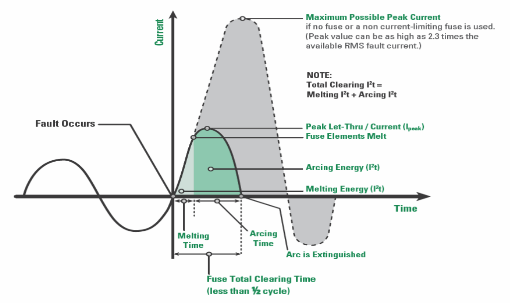
Current-limiting fuses reduce both the magnitude and duration of a fault current. A UL Listed, current-limiting fuse must clear a short circuit current in less than one half cycle. In its current-limiting range, the fuse will melt in the first quarter cycle, limiting the total electrical energy delivered to the fault.
Activity: Click through the images below to see a test conducted on a 48-V circuit breaker
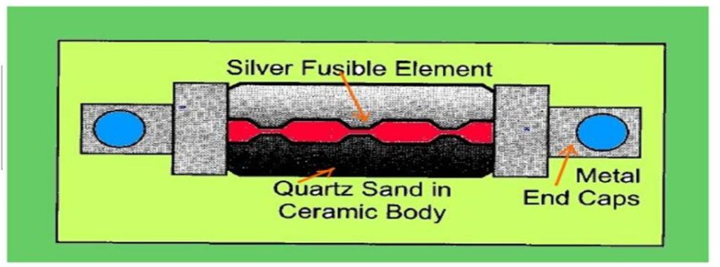
Current-Limiting Fuses use a silver ribbon element, surrounded by fine granular silica sand, housed in a fibreglass tube. During high levels of fault current, the element heats and vaporizes along much of its entire length. High temperature of the resulting arc melts the sand around the arc, forming a glasslike structure. Glass structure restricts the arc, causing the resistance of the fuse to increase dramatically. This added resistance changes the circuit power factor to near unity, which means current and voltage are in phase and cross the zero point at the same time.
North American Classes of Fuses
The North American fuse industry has developed a number of classes or standards for fuses with voltage ratings of 600 V or less.
North American Classes of Fuses
| UL Class | Fuse Overload Characteristics | Interrupting Rating, Amperes | AC Voltage Rating | Available Ampere Ratings |
| L | TIME-DELAY | 200,000 | 600 | 200 – 6000
601 – 4000 200 – 2000 |
| RK1*** | TIME-DELAY | 200,000 | 250
600 |
1/10 – 600 |
| FAST-ACTING | 200,000 | 250
600 |
1 – 600 | |
| RK5 | TIME-DELAY | 200,000 | 250
600 |
1/10 – 600 |
| T | FAST-ACTING | 200,000 | 300
300 |
1 – 1200 1 – 1200 |
| J | TIME-DELAY | 200,000 | 600 | 1 – 600 |
| FAST-ACTING | 200,000 | 600 | 1 – 600 | |
| CC | TIME-DELAY | 200,000 | 600 |
1/10 – 30 1/4 – 30 |
| FAST-ACTING | 200,000 | 600 | 1/10 | |
| CD | TIME-DELAY | 200,000 | 600 | 35 – 60 |
| G | TIME-DELAY | 100,000 | 480 | 1/2 – 60 |
| K5 | FAST-ACTING | 50,000 | 250
600 |
1 – 600 |
| H | Renewable Fuses Fast-Acting | 10,000 | 250
600 |
1 – 600 |