Part 8 – Power Factor
Power factor
The ratio of the actual power in watts to the volt-amperes (VA) of an AC circuit. True Power to Apparent Power. Value is dependent on how much the voltage and current are out of phase. The power factor is unity (1) when the voltage and current are in phase.
What is Power Factor?

The current flowing in an AC circuit is made up of two components:
- An active current component in phase with the voltage. When multiplied by the voltage, is the useful or actual value of the circuit.
- A reactive current component is out of phase with a voltage of 90°. Wattless as it adds no value to the actual power of the circuit.
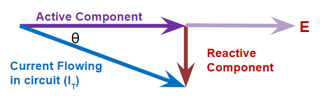
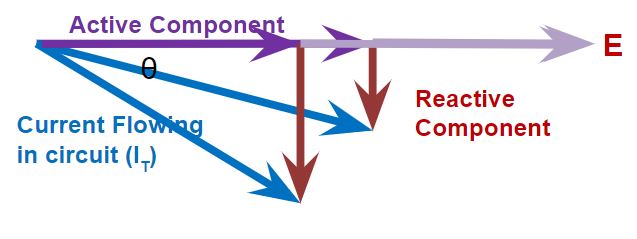
For a fixed value of IT, as phase angle θ increases
- Reactive component increases
- Active component decreases
Current Components
The cosine of the impedance phase angle θ is the ratio of the active current to the total current, or:

Or

Since the actual power is the voltage multiplied by the active component of the current:
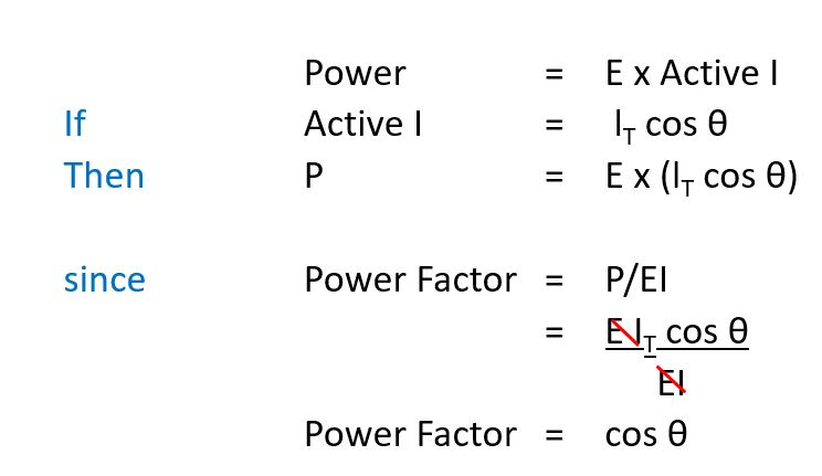
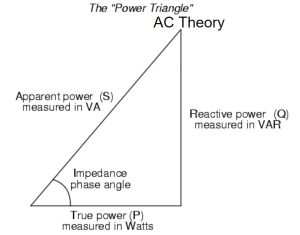
True power
Can be calculated:
True Power = Apparent Power (VA) x Power Factor.
- In watts or kilowatts
Apparent power
Product of the effective values of voltage and current in an AC circuit.
Apparent Power = I2Z
- In voltamperes (VA) or kilovoltamperes (kVA).
Purely resistive circuit
- Voltage and current are in phase.
- The power factor is 1.
Purely capacitive or inductive circuit
- Voltage and current are out of phase by 90°.
- The power factor is zero.
- Zero value of actual power.
Resistive and Reactive Circuits
- Have a power factor between 1 and zero.
- Value depends on the relative values of the circuit’s resistance and reactance.
Activity: Resistance Under Power
Click the arrows to learn more about resistance under power.
Example
A circuit with a coil having a resistance of 33 ohms and an inductance of 0.09 H is connected across a 600v, 60 Hz supply.
Calculate the power factor.
Solution
R = 33 ohms
L = 0.09 H
V = 600 v
f = 60 Hz
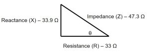
Reactance (X)
= 2πfL
= 2 x 3.14 x 60 x 0.09
= 33.9 Ω
Impedance (Z)
= √(R2 + X2)
= √(33)2 + (33.9)2
= 47.3 Ω
R = 33 ohms
L = 0.09 H
V = 600 v
f = 60 Hz
X = 33.9 Ω
Z = 47.3 Ω

R = 33 ohms
L = 0.09 H
V = 600 v
f = 60 Hz
X = 33.9 Ω
Z = 47.3 Ω
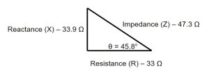
θ = 45.8o
Power Factor
= cos θ
= cos 45.8
= 0.697
Or

Power Factor Correction
Video: Power Factor Correction Explanation
Watch “Power Factor Correction Explanation” [5:41].
Low Power Factor
Low power factor is caused by inductive loads, for example, transformers, electric motors, and high-intensity discharge lighting.
A major portion of the power is consumed in industrial complexes. A low power factor causes more current to be required to supply a given kilowatt load at a low power factor than at a unity power factor. The lower the power factor; the higher the line drop and losses to transmit a given kilowatt load.
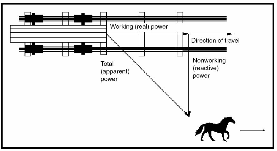
Inductive loads require the current to create a magnetic field, and the magnetic field produces the desired work. The total or apparent power required by an inductive device is a composite of:
- Real power (True), kW
- Reactive power, kVAR
The nonworking power caused by the magnetizing current, required to operate the device
Some strategies for correcting your power factor are:
- Minimize operation of idling or lightly loaded motors.
- Avoid the operation of equipment above its rated voltage.
- Replace standard motors as they burn out with energy-efficient motors. The motor must be operated near its rated capacity to realize the benefits of a high power factor design.
- Install capacitors in your AC circuit to decrease the magnitude of reactive power.
Capacitor
Video: The Capacitor
Watch “MAKE presents: The Capacitor” [8:00].
A device used to store charge in an electrical circuit.
- A passive electronic component that stores energy in the form of an electrostatic field.
- Functions like a battery, but charges and discharges much more efficiently. Batteries can store much more charge.
Made up of two conductors separated by an insulator, or dielectric.
- Dielectrics can be made of paper, plastic, mica, ceramic, glass, a vacuum, or nearly any other nonconductive material.
Capacitors store energy in the electric field between a pair of conductors (plates).
- Involves electric charges of equal magnitude, but opposite polarity, building up on each plate.
- Since the current drawn by a capacitor leads the applied voltage by 90o, the current drawn cancels the effect of the inductive reactive component of the load on the same circuit.
Values of capacitors are in volt-amperes reactive (VAR) – Reactive Power. The purpose is to counteract inductive loading from electric motors and fluorescent lighting in order to make the load appear to be mostly resistive.
Controlling Capacitors
The installation of a controller provides:
- Automatic switching of capacitor units
- Maintains the power factor under any operation or load changes.
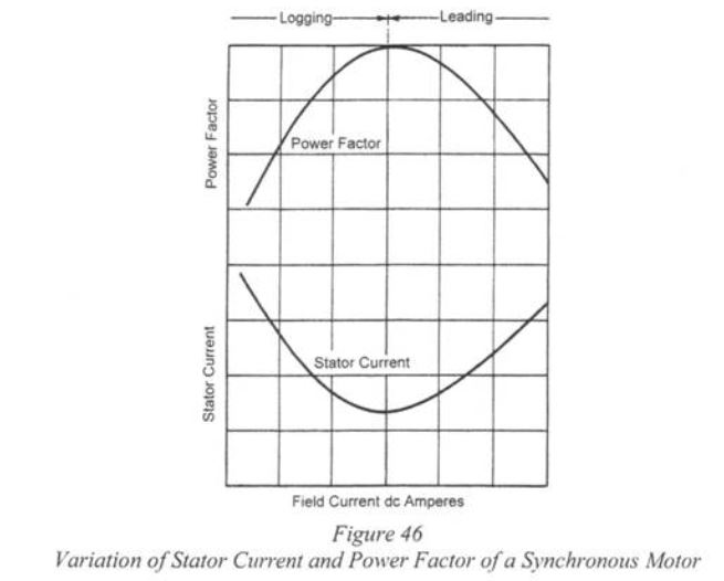
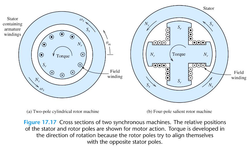
Synchronous Motors
Synchronous motors, also known as synchronous condensers, are utilized in three-phase circuits for power factor correction. These AC motors exhibit zero slip during typical operation, unlike induction motors that require slip to generate torque. Synchronous Motors either supply or absorb reactive power from the grid, serving as a valuable tool for power factor control.
Synchronous generators are a fundamental choice for electrical power plants due to their crucial role in maintaining a constant frequency. These generators can sustain consistent frequencies by adjusting their field excitation, allowing them to operate effectively across a wide range of power factors.
Field excitation is adjusted to allow the motor to operate at a unity power factor. Carrying the same mechanical load, the field excitation is increased. This causes the counter emf E to increase.
Motor Size
The installation of an oversized motor without proper power factor correction is a leading cause of low power factor.