Part 7 – Paralleling Transformers
Transformers can be paralleled to increase the kVA capacity of a power distribution system. Two three-phase 75 kVA transformers could be paralleled to provide 150 kVA, and the voltage ratings and kVA capacity of the transformers should be the same. Paralleling transformers must have the same winding configuration, and the transformers should have the same manufacturer.
If the impedance of the transformers is not the same, some current may circulate between the transformers – not all current is supplied to the load. This presents problems in sizing conductors that supply power to the load and in adequately protecting the system with fuses or breakers.
Short Circuit Current
If there is a short circuit in a power distribution system, the current in the system takes the path of least resistance. A short circuit current can reach very high levels if there is very little resistance in the system.
Winding Markings
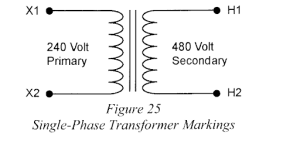
Winding markings are very important if transformers are to be paralleled. High-voltage windings of transformers are marked H, and low-voltage windings are marked X.
The high and low voltage sides of single-phase transformers are marked H1/H2 and X1/X2.
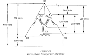
And the high and low voltage sides of three-phase transformers are marked H1/H2/H3 and X1/X2/X3.