Part 6 – Combined Circuits
Resistive, Inductive, and Capacitive Reactance
Resistance/Inductance Circuit
The circuit consists of resistance (R ohms) in series with inductance (L henrys).
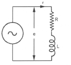
R is in phase with the current. The voltage applied to an inductance leads 90° in front of the current.
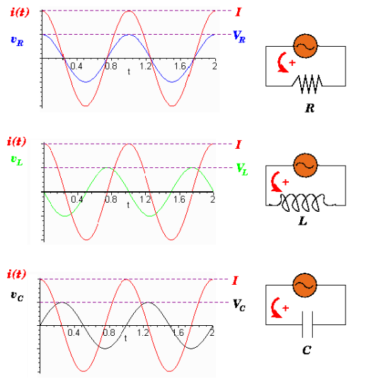
Activity: Voltage and Current Curves
Click the image hotspots to learn more about voltage and current curves.
SLIDE 6 – 12 – make a video explaining the contents and the graphics
Representation of an Alternating Quantity by a Rotating Vector
Capacitance
- XC = 1/2πfC
- XC = Capacitive reactance (Ω)
- f = Frequency (Hz)
- C = Capacitance (F)
Inductance
- XL = 2πfL
- XL = Inductive reactance (Ω)
- f = Frequency (Hz)
- L = Inductance (H)
Instantaneous Current
Vectors Representing Current and Voltage Differing in Phase
Addition of Alternating Voltages of Current Using Vectors
The addition of alternating voltages of current using vectors is a common practice in AC analysis. However, it’s important to note that the vector sum of OC is typically less than the arithmetical sum of OA and OB, unless OA and OB are in phase with each other. This phenomenon underscores why it is rarely accurate in AC work to simply add voltages or currents together arithmetically.
Application of Vectors to a Circuit Consisting of Resistance and Inductance in Series
Activity: Application of Vectors to a Circuit Consisting of Resistance and Inductance in Series
Click the ticks on the slider bar to learn more about the application of vectors to a circuit consisting of resistance and inductance in series.
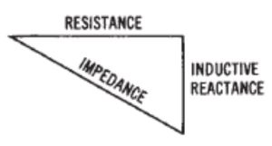
Calculation of Impedance – Resistance and Inductance in Series
Since the angle between OB and BE is a right angle:
OE2 = OB2 + BE2 = OB2 + OC2
Em2 = (R Im)2 + (2πfL Im)2
(R Im)2 = OB = Voltage across resistance
(2πfL Im)2 = OC = Applied voltage
Em = Im√(R2 + (2πfL)2)
= Im√(R2 + XL2)
And Em/Im = √(R2 + XL2)
If E and I are the effective (rms) values of the voltage and the current respectively, then:

Where
- R = Circuit resistance (ohms)
- XL = Circuit inductive reactance (ohms)
- L = Inductance (Henrys)
The impedance of any AC circuit is always given by the ratio of the voltage to the current and is represented by the symbol Z.
Z ohms = √(R2 + XL2)
Z ohms = E/I
I amperes = E volts / Z ohms
Activity: Vector Diagrams
Click the tick marks to learn more about Vector Diagrams.
When a circuit is non-inductive, its impedance is the same as the resistance. When the circuit consists of an inductor, the impedance is practically the same as the reactance.

Also

And

Capacitive/Reactance Circuit

Capacitive reactance is inversely proportional to capacitance and frequency.
Inductive Reactance (XL) = 2πfL
Inductive reactance is directly proportional to inductance and frequency.
Impedance in a Capacitive/Reactance Circuit
Example:
120 volts AC is connected across a 12 ohm resistor and a 100 μF capacitor.
Solution:
F = 60 Hz
C = 100 μF = 100 x 10-6 F
Capacitive reactance:
XC (ohms)
= 1/(2πfC)
= 1/(2 x 3.1416 x 60 x 100×10-6)
= 2.65 ohms
Impedance in a Capacitive/Reactance Circuit
Example:
120 volts AC is connected across a 12 ohm resistor and a 100 μF capacitor.

Solution:
Impedance is the vector sum of capacitive reactance and resistance:
Z=√(R2 + XC2)
=√(122 + 2.562)
=12.3 ohms
Current is the voltage divided by impedance
I=E/Z
=120/12.3
=9.76 amps
Impedance in a Capacitive/Inductive/Reactance Circuit
Impedance is the vector sum of capacitive reactance, Inductive reactance, and resistance:
XT=(XL – XC)
Z = √(R2 + XT2)
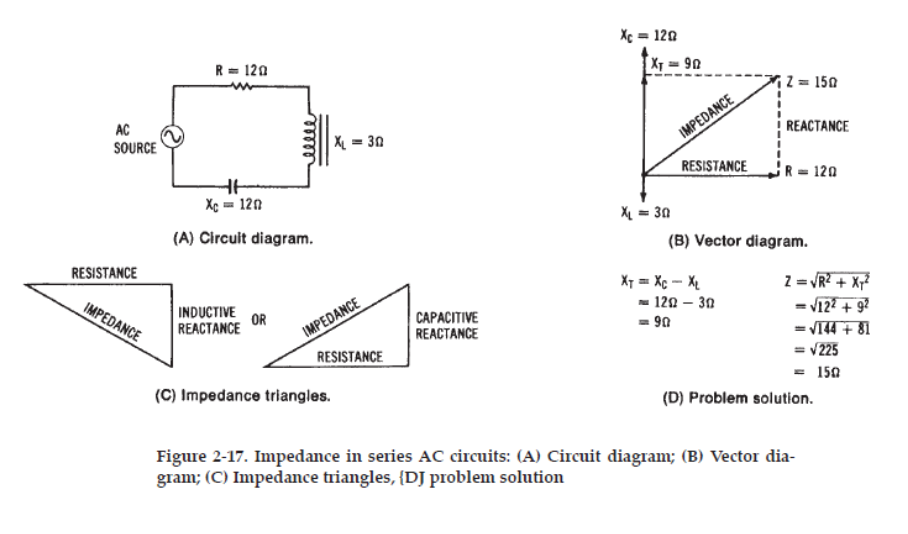
Example:
An AC circuit contains a resistance of 20 ohms connected in series with an induction coil of 80 mH and a 16 μF condenser (capacitor).
Find the total impedance when working on a 60 Hz power supply
Solution:
R = 20 ohms
L = 80 mH = 0.8 H
C = 16 μF = 16 x10-6 F
XT = (XL – XC)
XL = 2 π f L ohms
= 2(3.1416)(60 Hz)(0.8 H)
= 301.6 ohms
XC = 1/2 π f C
XC = 1/2(3.1416)(60 Hz)(16 x 10-6 F)
= 33.2 ohms
Solution:
R = 20 ohms
L = 80 mH
C = 16 μF
XL = 301.6 ohms
XC = 33.2 ohms
XT = (XL – XC)
= 301.6 – 33.2 ohms
= 268.4 ohms
Z = √(R2 + XT2)
= √(202 + 268.42)
= 170 ohms