Part 5 – Transformer Cooling
Transformer Cooling
Life expectancy is reduced if the operating temperature exceeds the rated temperature of the unit. A 10°C increase in temperature above the rated temperature will reduce the life of the transformer by 50%. Resistance increases with temperature. The most common methods of transformer cooling are air and oil.
Air Cooling
Air cooling is the smaller distribution transformers are the dry-type because their construction allows air to circulate through the core and coils.
Dry-type transformers have an input voltage of 600 v or less and some dry-type are filled with gas, i.E. Freon, that is used as a coolant. Transformer is filled with the gas and hermetically sealed.
Air Cooling Transformers
Go through the images to view different types of air cooling transformers.
The insulation system classification represents the maximum temperature permitted in the hottest spot in the winding when operated in a 40 °C maximum ambient. The hotspot temperature is determined by adding the maximum value for each of the following:
- 40 °C maximum ambient
- 150 °C maximum average winding rise
- 30 °C maximum hot spot in winding
- 220 °C ultimate temperature at hot spot
Transformer temperatures rise and apply to the conductor inside the coil and do not apply to the outside surface. Some customers will specify 220 °C insulation with 80°C or 115 °C rise to get overloaded capability, better efficiency, and longer life. These transformers are designed to operate with a lower rise per the following example:
80 °C maximum average winding rise
30 °C maximum hot spot in winding
30 °C thermal overload 30%
140 °C ultimate temperature at hot spot
Oil Cooling
Oil cooling is an oil-immersed type which is the core and windings are immersed in oil. Transformer oil is highly-refined mineral oil, stable at high temperatures, and has excellent electrical insulating properties.
Oil Cooling Transformers
Go through the images to view different types of oil cooling transformers.
Oil cooling cools the transformer and provides part of the electrical insulation between internal live parts. Oil cooling transformers must remain stable at high temperatures over an extended period. To improve the cooling of large power transformers, they have an oil-filled tank with external radiators. Very large or high-power transformers may also have cooling fans, oil pumps, and oil-to-water heat exchangers.
Oil Cooling transformers are large and high-voltage transformers. It needs to be totally dried to ensure that the transformer is completely free of water vapor before the cooling oil is introduced. Oil-filled transformers with conservators (an oil tank above the transformer) may use a forced oil cooling system. Also has safety relays that detect gas build-up inside the transformer and switch off the transformer.
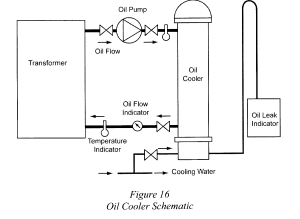
Here is a diagram that depicts the layout of an oil cooling system for a transformer.
Air and moisture in the conservator can be addressed by one of the following methods:
- The tank is vented through a breather pipe that contains a filter and a moisture-absorbing desiccant, such as a silica gel.
- The tank is slightly pressurized with a blanket of nitrogen or another inert gas.
- A flexible rubber diaphragm floats on the oil to seal it from the air.
For a transformer with a temperature rise of 55°C, the cooling system is designed to maintain an average winding temperature that is no more than 55°C above an ambient temperature of 30°C. Auxiliary fans may also be used for additional cooling capacity. In some operations, transformers are sprayed with water to keep them cool during hot weather.
Transformer Safety
It is crucial to maintain the cleanliness of transformer enclosures and the surrounding area to ensure proper functioning. Transformer vaults and rooms should not be utilized as storage spaces, as any items placed near or against the transformer can obstruct heat transfer around the enclosure. Additionally, the efficiency of heat transfer can be significantly reduced if dirt and grime accumulate on the surfaces of the transformer.
Cooling Classes
Having the cooling class of the transformer stamped on the nameplate is a requirement for the following:
- ANSI (American National Standards Institute),
- IEEE (Institute of Electrical and Electronics Engineers)
- NEMA (National Electrical Manufacturers Association)
- IEC (international Electrotechnical Commission)
Designated by letters:
- First Letter: Internal cooling medium in contact with the windings
- O – Mineral oil or synthetic insulating liquid with flash point less than 300°C
- K – Insulating liquid with flash point greater than 300°C
- L – Insulating liquid with no measurable flash point
- Second letter: Circulation mechanism for internal cooling medium:
- N – Natural convection flow through cooling equipment and windings
- F – Forced circulation through cooling equipment (cooling pumps), natural convection flow in windings (non-directed flow)
- D – Forced circulation through cooling equipment, directed flow from the cooling equipment into at least the main windings
- Third letter: External cooling medium
- A – Air
- W – Water
- Fourth letter: Circulation mechanism for external cooling medium
- N – Natural convection
- F – Forced circulation (fans, pumps)
Types of Cooling Systems
Ventilated, self-cooled transformers
- A ventilated, self-cooled transformers have air that circulates in through ports on the bottom and out through ports on the to and has no fan.
Self-cooled, plus forced air circulation
- A self-cooled, plus forced air circulation system has ventilation ports for fan inlets (filtered) and outlets only.
Ventilated, self-cooled
- A ventilated, self-cooled system has a fan or fans providing additional forced-air cooling. Fans may be wired to start automatically when the temperature reaches a pre-set value.
Self-cooled, non-ventilated (NV)
- A self-cooled, non-ventilated system has an enclosure that has no ventilation ports or fans and is not sealed to exclude migration of outside air. There are no provisions to allow outside air to enter and exit intentionally. Cooling is by the natural circulation of air around the enclosure and it may have some fins attached outside the enclosure to increase surface area for additional cooling.
Self-cooled, sealed with a gas inside
- A self-cooled, sealed with a gas inside system has an enclosure that is hermetically sealed to prevent leakage. Typically, the system has gas, such as nitrogen or Freon, to provide high dielectric strength and good heat removal. Cooling occurs through the natural circulation of air around the outside of the enclosure, which has no fans to circulate cooling air; however, there may be fins attached to the outside to aid cooling.
Oil-immersed and self-cooled
- An oil-immersed and self-cooled transformer windings and core are immersed in some oil and are self-cooled by the natural circulation of air around the outside enclosure. Fins or radiators may be attached to the enclosure to aid cooling.
Liquid-immersed, self-cooled/forced-air cooled
- A liquid-immersed, self-cooled/forced-air cooled transformer windings and core are immersed in some type of liquid and are self-cooled by natural circulation of air around the outside enclosure. Fins or radiators may be attached to the enclosure to aid cooling and the fans are usually mounted on radiators. The transformer usually has two load ratings, one with the fans off and a larger rating with the fans operating. The fans may be wired to start automatically at a pre-set temperature.
Liquid-immersed, self-cooled/forced air-cooled/forced liquid and forced-air cooled
- A liquid-immersed, self-cooled/forced air-cooled/forced liquid and forced-air-cooled system has windings and cores immersed in some type of oil. It also has radiators attached to the enclosure and self-cooling, natural ventilation, forced-air cooling fans, and forced-oil cooling (pumps) with additional forced-air cooling. There are three load ratings corresponding to each cooling step and fans and pumps may be wired to start automatically at pre-set levels as temperature increases.
Liquid-immersed, water-cooled
- A Liquid-immersed, water-cooled system is an oil/water heat exchanger (radiator) that is normally attached to the outside of the tank. Cooling water is pumped through the heat exchanger, but the oil flows only by natural circulation. As the windings heat the oil, it rises to the top and exits through piping to the radiator and as it is cooled, the oil descends through the radiator and re-enters the transformer tank at the bottom.
Liquid-immersed, forced-liquid cooled
- A liquid-immersed, forced-liquid cooled system normally has only one rating. It is cooled by pumping oil (forced oil) through a radiator normally attached to the outside of the tank and air is forced by fans over the cooling surface.
Liquid-immersed, forced-liquid cooled, water cooled
- A liquid-immersed, forced-liquid cooled, water cooled system is cooled by an oil/water heat exchanger normally mounted separately from the tank. Both the transformer oil and the cooling water are pumped through the heat exchanger to accomplish cooling.
Transformer Precautions
Some oils are flammable and require special fire suppression systems as a transformer precaution. If it is located within a building or on a rooftop, it will require a special dyke or drainage curb.