Part 5 – Alternator Protective Relays
Protective Relays
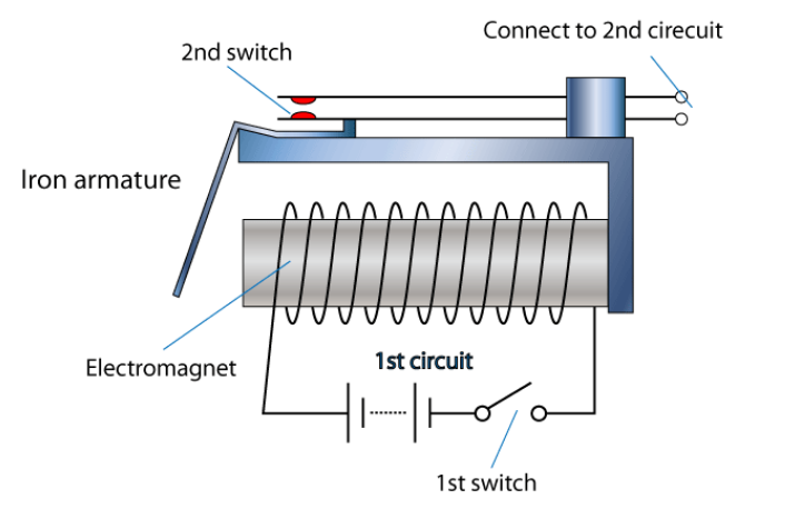
A solenoid is a device that produces mechanical motion from the energization of an electromagnet coil. The movable portion of a solenoid is called an armature.
A relay is a solenoid set up to actuate switch contacts when its coil is energized.
Classes of Relays
There are four classes of relays: auxiliary, protective, regulating and verification.
| Type of Relay | Description | Examples |
| Auxiliary relays | Used to assist other relays or devices to perform their function. | Timing relays, interposing relays, etc. |
| Protective relays | Used to detect faults and to initiate switching (i.e. send a signal to the breakers to open). | Overcurrent relays, impedance relays, etc. |
| Regulating relays | Used to detect a departure from a predetermined quantity and to initiate corrective action to get the quantity back to its limits. | Frequency relays, voltage relays used for voltage regulation, etc. |
| Verification relays | Used to verify conditions of the power system. | Alarm relays, etc. |
Another classification of the relays is according to their speed.
- High speed relays – operation time 3 cycles or less
- Low speed relays – operation time over 3 cycles
Video: Watch this video to learn about relay and contactor basics.
Types of Currents
Pull-in current
The minimum amount of coil current needed to actuate a solenoid or relay from its “normal” (de-energized) position.
Drop-out current
The maximum coil current below which an energized relay will return to its “normal” state.
Operation Principles
Some protective relays operate on the following principles:
-
- Electromechanical principle
- Solid state and microprocessor based
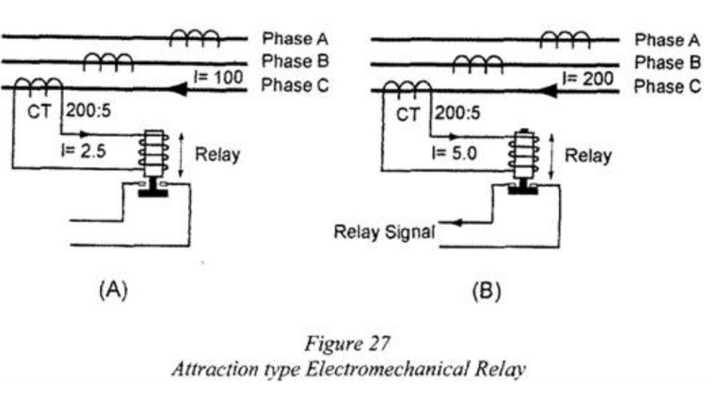
Attraction Type Electromechanical Relay
Click on the image below to learn the components of an attraction type electromechanical relay.
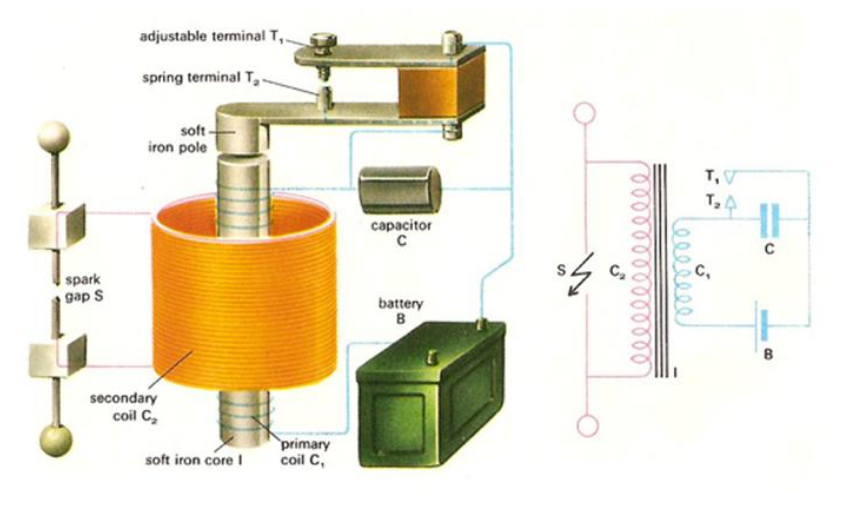
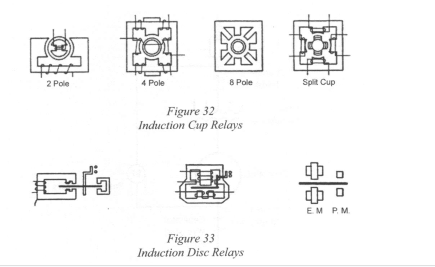
Induction Type Electromechanical Relay
Current signal from a current transformer flows in the stator windings. As current in one of the phases increases, voltage is induced in the disc, which cases a current to flow. The induced current produces magnetic fields in the stator. The interaction of the two magnetic forces produces torque that spins the disc. Contacts are closed and a signal is relayed if enough torque is produced to rotate the disc. The distance between the contacts can be adjusted to provide a time delay.
Activity: Click though the images to learn about how an induction type electromechanical relay works.
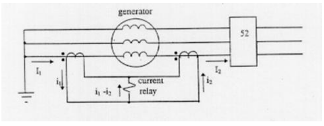
Differential Induction Disc Electromechanical Relay
An induction type coil monitoring current at both ends of a transmission line. A second coil is added and it’s stator will oppose the magnetic field of the first coil. The current should be the same in the coils and the rotor does not move. If there was a short circuit in either line, the currents would be different and the rotor would turn and close the contact to trip the breaker.
Activity: Click through the images to see how a differential induction disc electromechanical relay works.
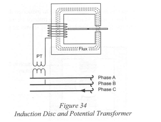
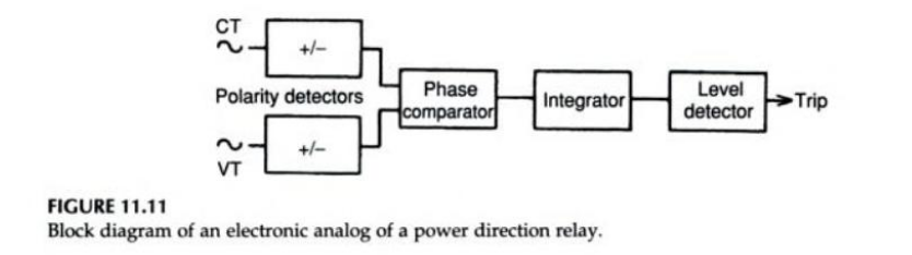
Directional relay
Directional relays are constructed using signals from two different actuation signals. Used to sense the direction of power flow. One signal is used as a reference and the other signal is used to polarize. If power flow changes direction, the relay is triggered.
Solid State Relays (SSR)
Solid state relays (SSR), or semiconductor relays are semiconductor devices that can be used in place of mechanical relays to send information. Solid state relays are significantly smaller and lighter and better suited to dusty conditions. Offer much more sophisticated protection than electromechanical relays.
Protective Relays
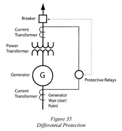
Differential Relays
Differential relays are used to sense the difference between two quantities. They are installed to monitor several types of faults:
- Faults between windings
- Stator ground faults
- Faults between phases of the bus bars.
Voltage Restrained Time Overcurrent
Used due to the nature of a fault such as a 3-phase fault to ground in a generator. Voltage and current both decay simultaneously in this type of fault. Necessary to have a protective relay that adjusts the trip point for overcurrent accordingly.
Loss of Excitation
Monitors for a loss of field excitation in the generator. When a generator loses its excitation, it starts drawing reactive current from the system it is supplying. Power factor changes when excitation is lost. Equipment can be calibrated to trip the generator output breaker if this condition exists.
Loss-Of-Synchronism Protection
When two power or interconnecting systems lose synchronism, there are large variations in voltages and currents throughout both systems. Voltages will be maximum and currents will be minimum when the systems are in phase. Voltages will be minimum and the currents maximum when the systems are 180 degrees out of phase. If an out of phase situation arises, the generator will be tripped.
Phase Current Unbalance
Generators are designed to deliver power to balanced three-phase loads. Severe unbalanced currents within the stator windings can cause harmonics. Leads to increased eddy currents and hysteresis losses. Severe overheating can occur in the stator. A phase current unbalance relay compares phase angles and trips coordinated breakers.
Underfrequency
When insufficient power is generated for the connected load, underfrequency results during heavy load demand. The drop in voltage causes the voltage regulator to increase excitation, which causes overheating in both the stator and rotor. At the same time, more power is being demanded and the generator is less able to supply it at the reduced frequency. Load shedding is the primary protection against generator overloading. Underfrequency relays should be used to provide additional protection.
Stator Ground Fault
Insulation failure is one of the most common sources of generator faults. Important to monitor for any non-standard current that may flow from the stator windings to ground. Current could be very small in magnitude but may indicate a serious fault is about to happen.
Resistance Grounding
Resistance grounding falls into two categories: low and high.
There are two categories of resistance grounding:
| Low-resistance grounding | High-resistance grounding |
| A fault in a low-resistance grounding system will allow enough current to operate a protective relay. | Fault currents are low in magnitude so resistance grounding won’t work. |
Reverse Power
The direction of normal power flow is from a generator to a load. If power conditions change in a parallel generator scheme it may cause the generator to act as a motor. Reverse power relays are sensitive to the real power component and insensitive to the reactive power component. If power is reversed, the torque produced in the relay will reverse and cause a trip.
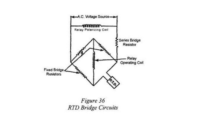
Stator Overheating
Stator overheating is caused by overloading or failure of the cooling system. Resistance temperature detector (RTD) coils or thermocouples are embedded in the slots with the stator windings of generators larger than 500 to 1000 kVA. Several of the detectors that give the highest temperature indications are selected for use with a temperature indicator or recorder, usually with alarm contacts. The detector giving the highest indication may be used to operate a temperature relay to sound a alarm.
Overspeed
The overspeed element operates the speed governor to shutdown the prime mover. Should also trip the generator circuit breaker. Prevents overfrequency operation of the generator itself from the AC system.
Phase Fault Protection
Primary protection for generator phase-phase faults is provided by differential relays. Differential relays detect phase-phase faults, three-phase faults, and double phase-to-ground faults.