Part 5 – Capacitive Circuits
Voltage, Current, And Power In Purely Capacitive Circuits
Capacitors
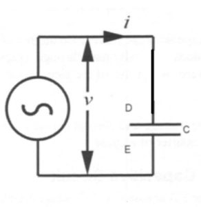
Capacitors do not behave the same as resistors. Resistors allow a flow of electrons through them directly proportional to the voltage drop. Capacitors oppose changes in voltage by drawing or supplying current as they charge or discharge to the new voltage level.
Video: The Capacitor
Watch “MAKE presents: The Capacitor” [8:00].
The flow of electrons “through” a capacitor is directly proportional to the rate of change of voltage across the capacitor. This opposition to voltage change is another form of reactance, one that is totally opposite to the kind exhibited by inductors.

Activity: Voltage and Current Curves for Capacitive Circuits
Click the image hotspots to learn more about voltage and current curves for capacitive circuits.
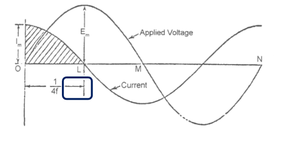
The current does not really pass through a capacitor. The current leads in front of the voltage by a quarter of a cycle.

If Im is the maximum value of the current:
Average current = 2/π x Im
and C x Em = 2/π x Im x 1/(4f)
sort Em/Im = 1/(2πfC) = Xc = capacitive reactance
f = frequency (Hz)
C = capacitance (Farads)
RMS values of the PD and Current respectively:
![]()
= 1/(2πfC) ohms
= XC
![Rendered by QuickLaTeX.com \Large \[I = \frac{E}{X_C} = \frac{E}{1/\left(2\pi fC\right)}\]](https://ecampusontario.pressbooks.pub/app/uploads/quicklatex/quicklatex.com-5542a2b62da8aaca2ac86bf409b59412_l3.png)
Current I = 2πfCE
Circuit capacitive reactance (XC) = 1/(2πfC) ohms
where:
- f = frequency (Hz)
- C= capacitance (Farads)
- π = 3.1416
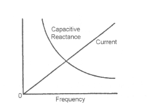
Capacitive reactance is inversely proportional to the capacitance and to the frequency of the supply voltage. Inductive reactance is directly proportional to the inductance and to the frequency.

