Part 4 – Switches and Contactors
Switches
Switches are devices for isolating parts of an electric circuit. Switches must be operated manually. Switches rated to interrupt continuous current, are classified as interrupting and disconnect switches.
Video: Watch the basic concepts of switches, poles and throws.
Interrupting types of switches are also called:
- Safety switches
- Isolating switches
- Disconnect switches
- Load-break switches
Electrical Safety
Most electrical codes require that a motor can be isolated or disconnected from its power source while maintenance is carried out. Provides safety in the event that power must be quickly removed from the motor and the breaker is located some distance away. In the off position, the switch prevents power from being inadvertently restored.
Interrupting switches are clearly labeled with a continuous current carrying capacity. Often, the switches are horsepower rated or kilowatt rated so that a switch with the proper capacity can be matched with the characteristics of the motor. An interrupting switch is designed to make or break the circuit while it is operating under full load. Fuses are incorporated and placed in series with the switches. This “safety switch”, provides overcurrent protection and serves as an isolating mechanism.
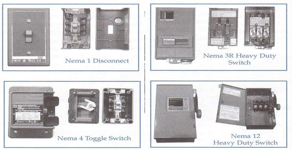
Sometimes, a spring mechanism is linked with the operating handle of a switch. Assists in breaking the arc generated when a switch is operated while under load. Switches designed for interrupting rated current in higher voltage applications use arc chutes.
Contactors
Magnetic contactors are used to switch loads. Similar to relays, but designed to operate under higher voltage ratings and current ratings. Contactor is used to switch a large amount of electrical power through its contacts. Typically has multiple contacts. Most common industrial use for contactors is the control of electric motors.
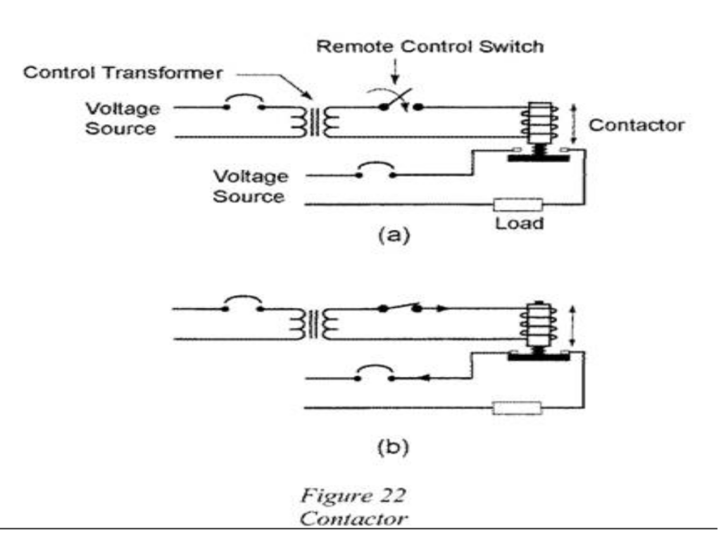
Used in applications where the switching feature is controlled from a remote location. A magnetic contactor uses the principle of an electromagnet to open or close a circuit.
Usually, a control transformer supplies a low voltage such as 24V or 120V to the remote switch. Magnetic contactors are used for motors up to about 75 kW to accomplish automatic starting, stopping, and reversing.
Activity: Click on the image to view the components of a magnetic contactor.
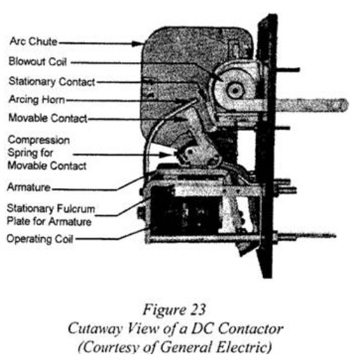
When energized, the operating coil pulls on the armature, causing the contact to close. The blowout coil is connected in series with the stationary contact and provides a magnetic flux to blow the arc up the chute where it is extinguished by elongation and cooling when the contacts are opened.
Wear on the stationary and movable contacts is reduced by the arcing horn, which takes the brunt of the burning. The blowout coil shifts the arc to the arcing horn and the upper curved part of the stationary contact where it is extinguished.