Part 4 – Parallel Operation of DC Generation
Parallel Operation Of Shunt Generators
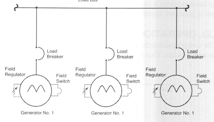
Generators are often operated in parallel to satisfy load demands. When the load varies, generators can be switched from off-line to on-line or vice versa.

Putting the Generator On-line
- Close the field switch and engage the prime mover.
- Adjust the voltage of the incoming machine to equal the bus voltage.
- Close the load breaker when the two voltages are equal.
This procedure is satisfactory for paralleling shunt, under-compounded, and flat-compounded machines.
Raise the voltage of the incoming shunt generator slightly above the bus voltage to ensure that it is taking load at the instant the load breaker is closed. Not necessary for both the flat and under-compounded machines because the series field helps to build up voltage quickly when the units are brought on-line.
Check output terminals of DC generator polarity, especially if a new generator has been installed or an existing generator has been repaired. Once on-line, the load can be shared or balanced by adjusting the field rheostats.
The operating speed of DC generators, operating in parallel, can vary. AC generators are more speed-dependent because they must produce a constant frequency.
Parallel Operation Of Compound Generators
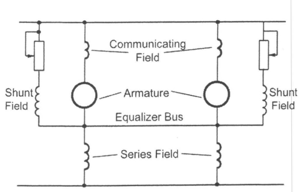
For compound machines to operate successfully in parallel, it is necessary to parallel their series fields. Use an equalizer connection.
Activity: Two-Wire Compound Generators in Parallel
Click the accordion to learn more about two-wire compound generators in parallel.

Without an equalizer:
- It’s hard to balance the load between the two parallel generators
- If you adjust the load by the field rheostat, the machine taking load could take the entire load and drive the other generator as a motor.
Using an equalizer:
- The total bus current is divided by the series fields in the inverse ratio of their series-field resistance.
- Because of its lower series-field resistance, the series field of the larger machine will take a higher percentage of the bus current.
Voltage Control
Increasing or decreasing the resistance of the field windings changes the voltage output. The voltage can be controlled automatically or manually.
Manual Voltage Control
- Uses a rheostat connected in series, parallel, or series/parallel with the field windings.
- Increasing the rheostat resistance – lowers the output voltage
- Decreasing the rheostat resistance – increases the output voltage
Rheostat
- Numerous turns of resistance wire wound around an insulated tube above which a metal bar was positioned.
- A sliding contact connected the wire to the bar.
- The sliding contact could be moved to change the amount of coiled wire an electric current traveled through before it was passed on to the bar, which was less resistant to flow.
- The rheostat allows the field current to be changed by changing the resistance.
Automatic Voltage Regulator (AVR)
- Useful for sudden voltage changes.
- Allows an operator to enter a desired voltage (setpoint).
- Makes changes to the field current based on: the magnitude of the error (difference from setpoint) and how fast the error is increasing or decreasing.
Voltage Regulation
Voltage regulation is based on the difference between the output voltage at no load and at full load.
- Determined while the generator is running at a constant speed.
Voltage Regulation (%) =
- The best regulation is obtained with a flat-compounded machine.
- The series machine has very little regulation.
