Part 4 – Alternator Voltage Regulation
Voltage Regulators
The purpose of automatic regulator equipment is to:
- Control the system voltage within prescribed limits.
- Regulate the division of reactive power shared between machines running in parallel.
- Control the field circuit closely to keep the machine in synchronism with the system when operating at near unity or leading power factor.
- Boost the excitation under system fault conditions to keep the machine in synchronization with the system.
Watch: Voltage Regulator – How it Works Part 2
Watch “Voltage Regulator – How it Works Part 2” [1:03].
Voltage regulators serve the purpose of automatically controlling the terminal voltage of the generating machine. It’s important to note that AC machines inherently possess a higher internal reactance in comparison to DC machines. To achieve this voltage control, most regulators incorporate magnetic amplifying components.
The output voltage can only be maintained approximately constant, and this regulation is determined by two key measurements:
- Load regulation, which signifies the change in output voltage for a given change in load current.
- Line regulation, or input regulation, denotes the extent to which the output voltage varies in response to changes in the input (supply) voltage, expressed as a ratio of output change to input change.
Video: Voltage Regulator – How it Works Part 1
Watch “Voltage Regulator – How it Works Part 1” [1:00].
In an AC generator, the output voltage is managed by adjusting the intensity of the rotating DC field. Enhancing the field strength results in higher AC output voltage, while reducing the DC field strength lowers the output voltage. As the generator load grows, it becomes necessary to increase the field strength to maintain a steady output voltage.
Voltage Regulation Methods
- Direct-Acting Rheostat Regulator
- Indirect Acting Regulator
- Electromechanical
- Electronic
- Amplidyne
- Power amplifier
Direct-Acting Rheostat Regulator
Direct-acting rheostat regulators depend upon the adjustment of variable resistances in the field circuit of the main exciter.
Activity: Direct-Acting Rheostat Regulator
Click the tick marks on the slider to learn more about the direct-acting rheostat regulator.
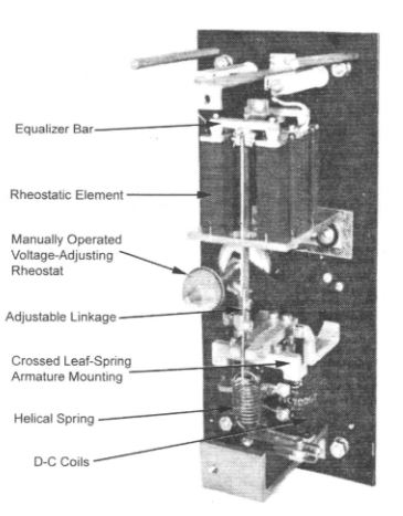
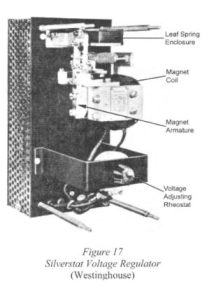
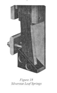
The Silverstat voltage regulator is a direct-acting rheostatic type of voltage regulator that employs a series of silver-buttoned leaf springs. These leaf springs close or open their contacts in succession to regulate voltage.
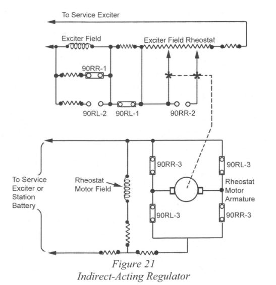
Indirect Acting Regulator
Activity: Indirect-Acting Regulator
Click the image hotspots to learn more about indirect-acting regulators.
Electromechanical Voltage Regulators
Disadvantages:
- The response time of the regulator and the equipment necessary to change the voltage variation signal into a mechanical force and act on the main exciter field is too great.
- The dead band is not acceptable for steady-state conditions when generators are running near the stability limit.
- As machines get larger in output, the increasing power in the excitation circuits makes it difficult for the regulator contacts to handle
Electronic Regulators
Early designs of electronic regulators featured a bridge circuit comprising two fixed and two variable arms. This bridge was powered by the reference voltage, with the other two bridge terminals providing the error voltage, indicating the difference between the existing value and the predetermined setting.
The error voltage from the bridge is input into an electronic amplifier, which can be implemented using a grid of thyratrons to control the field current flow. Thyratrons are specialized gas-filled tubes used as high-energy electrical switches and controlled rectifiers.
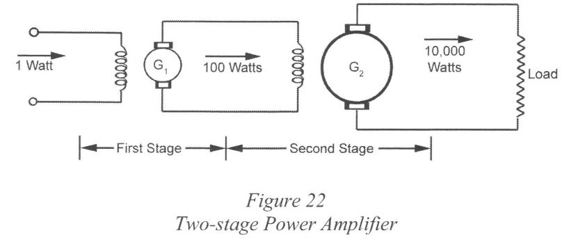
In a typical power amplifier, a DC generator is configured to consume 1 watt in the field circuit, with an anticipated output load of 100 watts. This output can then be supplied to the field of a second generator, resulting in another 100:1 ratio, equating to a total power amplification of 10,000:1.
However, a significant drawback of this setup is the considerable time required to effect the change in output. The time delay in a two-stage amplification process is approximately 1 second, which is considered too slow.
Amplidyne
DC generator of special design that combines in one machine a greater amplification than the two-stage amplifier together with ten or twenty times the speed of response.
A special type of motor generator, known as an Amplidyne, functions as a power amplifier. It features a separately excited field, allowing for slight adjustments in excitation power, referred to as the input or control signal. These minor changes in the input signal result in a substantial variation in the output power. Using this method, power amplification ratios as high as 250,000:1 can be achieved.
Normal Voltage Regulation
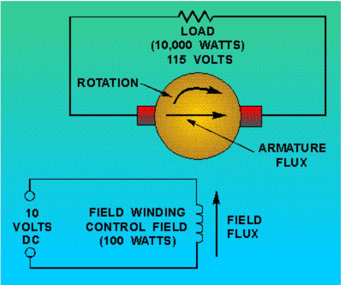
The field winding producing a control field of 100 watts produces 10,000 watts in the generator.
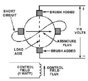 The operation of an Amplidyne involves shorting out the brushes, which effectively removes the resistance in the armature circuit. Then, a new set of brushes is introduced, referred to as the output brushes. These output brushes align with the armature flux, allowing them to pick off the voltage induced in the armature windings. As a result, the voltage at the output remains consistent with that of the original generator, but with significantly reduced input, going from 100 watts down to just 1 watt.
Activity: Amplidyne
Click the tick marks on the slider to learn more about amplidyne.
Magnetic Amplifier Regulator
Magnetic amplifier regulators consist of:
- A voltage reference circuit.
- A two-stage magnetic amplifier, power transformer, and rectifier.
Reference Circuit
A reference circuit consists of:
- A three-phase rectifier
- A Potentiometer
- A bridge circuit made up of two fixed resistors and two glow-discharge tubes.
A glow-discharge tube, commonly referred to as a VR tube, is employed to maintain a constant voltage in a circuit despite fluctuations in line voltage or load. When a certain voltage is applied across its electrodes, the gas ionizes, creating a glow discharge around the cathode electrode. This ionization effect transforms the VR tube into a negative resistance device. As the current passing through it rises, the ionization level increases, causing the device’s resistance to decrease further. Consequently, the VR tube conducts enough current to uphold the desired voltage across its terminals.
Voltage Reference Circuit for Magnetic Amplifier
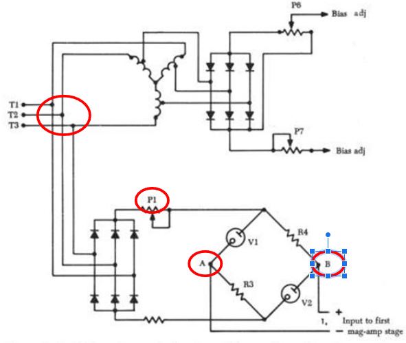
Potentiometer P1 is adjusted to maintain zero potential difference between points A and B at the rated bus voltage. Under any other input voltage, the potential arises between points A and B due to the voltage drop across the glow-discharge tubes. If the generator voltage is low, the current in the bridge’s arms decreases. The voltage across R4 is then lower than the fixed voltage across V1, resulting in point B having a higher potential than point A. This potential disparity generates an error signal used as input for the initial mag amp (magnetic amplifier) stage, with the error signal’s polarity reversing for high input voltages.
Advantages:
- Minimum of moving parts
- No electronic components
- Regulator is built entirely of static components
- Time response is very rapid, and there is no dead band.
- This regulator works from the difference between the generator terminal voltage and a fixed reference voltage. The difference between these two voltages is amplified by magnetic amplifiers in series and fed directly to correct the main exciter field current.
Static Excitation System
Automatic Voltage Regulator
An automatic voltage regulator (AVR) is a device responsible for automatically adjusting the generator’s excitation, ensuring that the terminal voltage remains within acceptable limits. It achieves this by promptly detecting any voltage variations and swiftly responding to deviations between the measured voltage and the desired voltage.
Voltage regulation is expressed in percent by the following formula:

Modern voltage regulators maintain voltage within +/- 1.5%.
Older voltage regulators have been replaced by static excitation systems and digital voltage regulators. There are no moving parts in a static voltage regulator system.
Activity: Static Excitation and AVR
Click the ticks on the slider to learn more about static excitation and AVR.
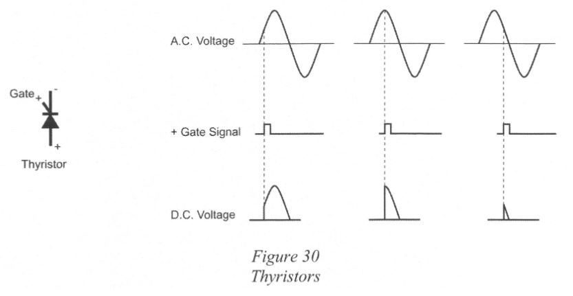
Thyristors
Similar to diodes but are designed with a gate that allows the amount of rectified DC voltage to be varied.